Skip to content
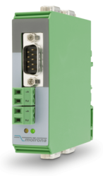
Features
SSI input with format DATA+, DATA-, CLOCK+, CLOCK-
SSI clock frequencies up to 1 MHz
Master or Slave operation
For single-turn and multi-turn encoders with 10 … 32 Bit
3 control inputs for HTL / PNP signals
Power supply 18 ... 30 VDC
5 / 24 V auxiliary output for encoder supply
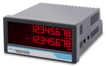
3.78 x 1.89-inch norm panel housing and IP65 protection
Bright and high-contrast display with event-dependent color variations
Emulation of a 7-segment display inclusively icons and units
Intuitive and easy parameterization by plain text and touchscreen
Operating modes such as scaling, bit blanking and wire break monitoring
Linearization with 24 control points
Options
Option AC: Power supply 115 ... 230 VAC
Option AO: 16-bit analog output, 4 control outputs, serial RS232 interface
Option AR: 16-bit analog output, 4 control outputs, serial RS485 interface
Option CO: 4 control outputs, serial RS232 interface
Option CR: 4 control outputs, serial RS485 interface
Option RL: 2 relay outputs
Options can be combined
Features
4 independent input channels with format A, B, C, D [HTL] or A, /A, B, /B, C, /C, D, /D [RS422], also possible for single-channel
4 output channels with format A, B, C, D [HTL] or A, /A, B, /B, C, /C, D, /D [RS422]
Maximum input frequency 1 MHz
Very short conversion time < 300 ns
Optical wavelength 1300 nm
Transmission distance up to 3000 meters
Power supply 5 VDC (for LW213)
Power supply 10 ... 30 VDC (for LW213-1, LW213-2, LW213-3)
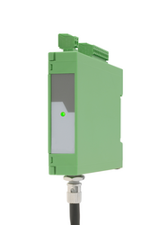
Snap-on housing for top-hat rail (according to EN 60715)
Pre-configured optical fibres are available
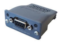
Features
Internal power supply 3,3 V
Ambient temperature 0° C ... +60° C / 32° F ... 140° F (operating), -40° C ... +70° C / -40 ... 158° F (storage)
9600 Bit/s ... 12 MBit/s Baud rates
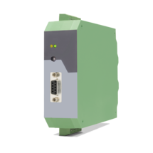
SUB-D-9-pin female, galvanically isolated
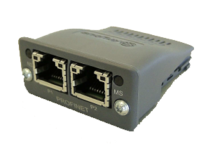
Features
Internal power supply 3,3 V
Ambient temperature 0° C ... +60° C (operating), -40° C ... +70° C (storage)
100 MBit/s Vollduplex
2 Ethernet-Ports RJ45 with integrated switch, galvanically isolated
Features
Encoder input with format SIN+, SIN-, COS+, COS-, REF+, REF- [1 Vss]
Control input „Error Release“ for PNP signals [10 ... 30 VDC]
Input frequency up to 400 kHz
Pulse output with format A, /A, B, /B, Z, /Z [RS422] or with format A, B, 90° [HTL]
Output frequency up to 4 MHz [RS422]
Control output „Error“ with push-pull characteristic, short-circuit-proof, [5 ... 30 VDC]
Power supply 18 ... 30 VDC
Snap-on housing for top-hat rail (according to EN 60715)
Adjustable multiplier for interpolation rates from 1:5 to 1:50
Adjustable divider 1:1 – 1:255 to reduce the output frequency
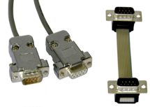
Features
1 connector Sub-D-9 (male)
1 connector Sub-D-9 (female)
cable length 3 m (approx. 10 feet)
Features
1 encoder input with format SIN+, SIN-, COS+, COS-, REF+, REF- [1 Vss]
Maximum sinus input frequency 500 kHz with max. 200 ns conversion time
2 signal outputs with format SIN+, SIN-, COS+, COS-, REF+, REF- [1 Vss]
2 pulse outputs with format A, /A, B, /B, Z, /Z [RS422, TTL, HTL]
Power supply 17 ... 30 VDC
Snap-on housing for top-hat rail (according to EN 60715)
Features
1 encoder input with format SIN+, SIN-, COS+, COS-, REF+, REF- [1 Vss]
Maximum sinus input frequency 500 kHz with max. 200 ns conversion time
4 signal outputs with format SIN+, SIN-, COS+, COS-, REF+, REF- [1 Vss]
Power supply 17 ... 30 VDC
Snap-on housing for top-hat rail (according to EN 60715)
Features
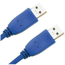
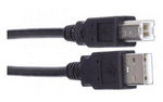
USB cable for connection between PC and the Motrona unit UZ210
Both connectors are type A
Cable length 2 m (approx. 6.5 feet)
Features
USB cable for connection between PC operator software and Motrona DS device
USB connector type A on type B
Length 1,8 m
Features
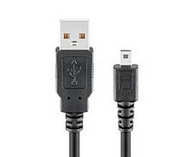
USB cable for connection between PC and Motrona devices of the series IV/FU/PV/ZU210 and IP/FP/PP/ZP210
USB connector type A on type Mini B
Length 1,8 m
Features
Scalable 14 bit analog input for ±10 V or 0/4 ... 20 mA
4 control inputs for PNP signals [10 ... 30 VDC]
Pulse output with format A, B, 90° [HTL] or A, /A, B, /B, Z, /Z [RS422]
SSI output with format DATA+, DATA-, CLOCK+, CLOCK- up to 25 bit
Power supply 12 ... 30 VDC
Snap-on housing for top-hat rail (according to EN 60715)
Various user modes: Programmable V / f characteristics, programmable curves with optionally repeating curve cycles, additional control functions similar to a “motorized potentiometer”
USB, RS232 and RS485 interface for programming and serial readout of the conversion result and other internal registers
Adjustable filter functions as well as operator programmable linearization curves
Printer mode for automatic data transfer of internal registers to a data logger or PC
Features
Pulse inputs A, B [HTL], A, / A, B, / B [RS422, HTL]
SSI input in the format DATA +, DATA-, CLOCK +, CLOCK- up to 32 bits
Start-stop interface for absolute transducers and magnetostrictive sensors
3 control inputs (hold) for PNP signals [10 ... 30 VDC]
Input frequency up to 1 MHz
25-bit parallel output push-pull in BCD, binary or Gray code format
Power supply 18 ... 30 VDC
Compact housing for mounting on 35 mm top-hat rail (according to EN 60715)
Features
Pulse inputs A, B [HTL], A, /A, B, /B [RS422, HTL]
Input frequency up to 1 MHz [RS422], 200 kHz [HTL]
Analog output ±10 V or 0/4 ... 20 mA, 16 Bit
Power supply 18 ... 30 VDC
Snap-on housing for top-hat rail (according to EN 60715)
Setup via operator software OS6.0
Serial RS232- / RS485 interface
SSI input DATA+, DATA-, CLOCK+, CLOCK- [RS422], 32 Bit
Start-stop interface for absolute transducers and magnetostrictive sensors
USB interface and RS232/RS485 interface for configuration and serial readout
Page load link