Skip to content
Features
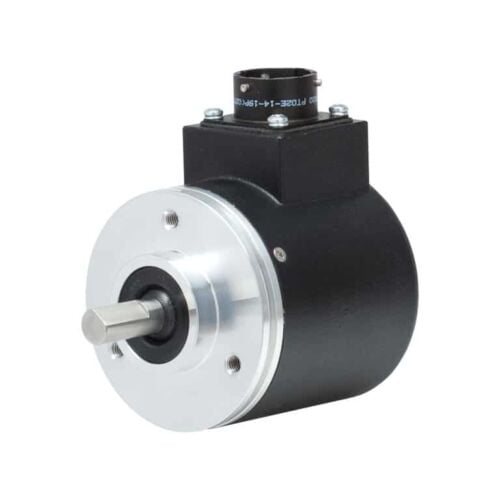
Standard Size 25 package (2.5")
Resolutions up to 12-bit (4096 counts)
Incorporates Opto-ASIC technology
Industrial-grade, heavy-duty housing
Optional IP67 seal
Features
Low profile—40mm
Thru-bore or hollow-bore styles
Industrial-grade, heavy-duty housing
State-of-the-art Opto-ASIC circuitry
Features
Standard Size 36mm package (1.42")
Durable magnetic technology
Multiturn absolute encoder (12-bit/39-bit)
SSI and CANopen communications
Proven new turns counting technology — no gears or batteries
Features
Standard Size 36mm package (1.42")
Durable magnetic technology
Multiturn absolute encoder (12-bit/39-bit)
SSI and CANopen communications
Proven new turns counting technology — no gears or batteries
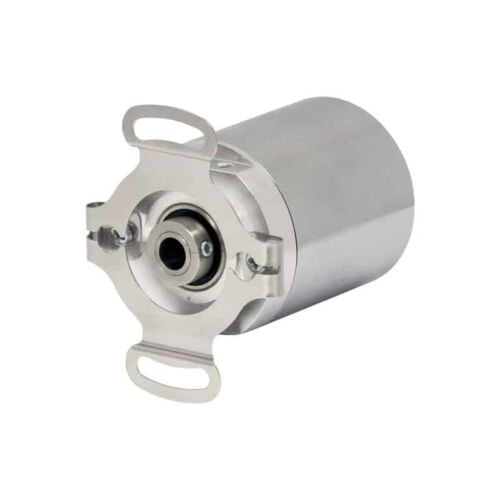
Features
Multi-Turn Absolute Encoder (14 Bit/39 Bit)
SSI and CANopen Communications
58 mm Diameter
Durable Magnetic Technology
Proven Turns Counting Technology – No Gears or Batteries
Retains Absolute Position After a Power Outage
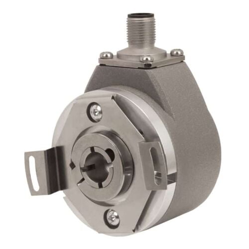
Features
Standard Size 36mm package
Durable magnetic technology
Up to 14 bits of single-turn resolution
SSI and CANopen communications
Proven turns counting technology—no gears or batteries
Flex mount eliminates couplings and is ideal for motors or shafts
Features
Standard size 36 mm package (1.42")
Durable magnetic technology
Up to 14 bits of single-turn resolution
SSI and CANopen communications
Proven new turns counting technology — no gears or batteries
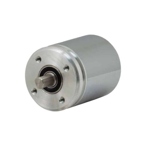
Features
Up to 14 Bits of Single-Turn Resolution
SSI and CANopen Communications
58 mm Diameter
Durable Magnetic Technology
Retains Absolute Position After a Power Outage
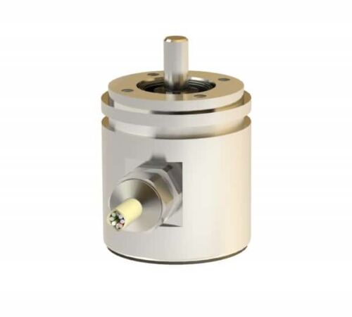
Features
Robust aluminium or stainless steel housing (wall thicknesses up to 5 mm)
Stainless steel shaft and ball bearing - ball bearing with Simmer ring
Rotor with shaft and permanent magnet mounted in pre-chamber
Sensor circuit consisting of ASIC
Hall elements and interface electronics in enclosed main chamber
Housing protection type IP 69K additionally cast
Electrical connection via cable (open cable ends)
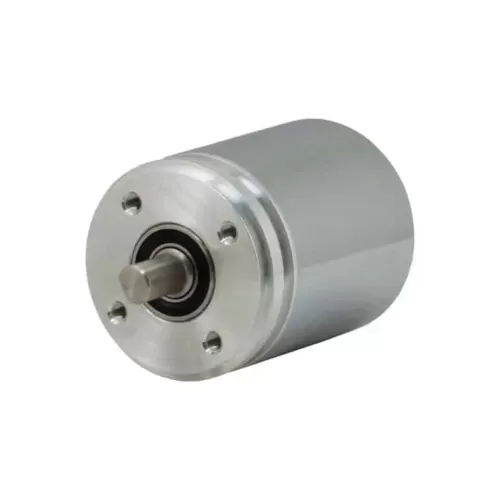
Features
Interface: SSI
Design: 42mm
Housing Material: Aluminium, stainless steel
Flange & Shaft: Synchroniser flange
Resolution: 4096 steps/360°<)
Code type: Binary, Gray (optional)
Electrical connection: Cable 1m
Electrical and/or mechanical variant: Basic version
Features
Robust aluminium or stainless steel housing (wall thicknesses up to 5 mm)
Stainless steel shaft and ball bearing - ball bearing with Simmer ring
Rotor with shaft and permanent magnet mounted in pre-chamber
Sensor circuit consisting of ASIC
Hall elements and interface electronics in enclosed main chamber
Housing protection type IP 69K additionally cast
Electrical connection via cable (open cable ends)
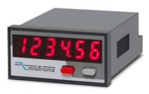
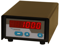
Features
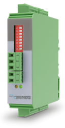
Scalable 14-bit analog input for 0 ... 10 V or 0/4 ... 20 mA
Power supply 24 VDC
Miniature norm panel housing
5 digits LED display with 8 mm height
Display range -19999 ... 99999, adjustable zero and full-scale value
Latch input to freeze the display, minimum/maximum record memory
Easy to set up with only two front keys and menu support
Delivery includes adapter frame for 50 x 25 mm cut out and label set with dimensions
Front dimension 48 x 24 x 59 mm (1.89 x 0.945 x 2.322")
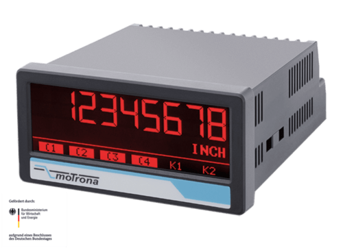
Features
2 universal 16-bit analog inputs for ±10 V or 0/4 … 20 mA
3 control inputs for HTL / PNP signals
Power supply 18 ... 30 VDC
24 V auxiliary output for encoder supply
High accuracy reference output 10 V for potentiometers > 1 kOhm
3.78 x 1.89-inch norm panel housing and IP65 protection
Bright and high-contrast display with event-dependent color variations
Emulation of a 7-segment display inclusively icons and units
Intuitive and easy parameterization by plain text and touchscreen
Operating modes for visualization of INPUT 1, INPUT 2 or combinations of IN1 + IN2, IN1 - IN2, IN1 x IN2, IN1: IN2
Numerous features, e. g. Ttara, filters, averaging
Linearization with 24 control points
Option IO (= IO-Link Device)
Data transfer via COM3 (230,4 kBaud)
Cycle times < 3 msec
Process data IN 32 Byte (6 x process values from AX350):
- Analog value 1 (scaled / linearized) and unit
- Analog value 2 (scaled / linearized) and unit
- Analog value 1 (scaled / linearized) with totalisation and unit
- Analog value 2 (scaled / linearized) with totalisation and unit
- Shortcut analogue value 1 (scaled / linearized) with analogue value 2 (scaled / linearized) and unit
- Shortcut totalisator analogue value 1 (scaled / linearized) with totalisator analogue value 2 (scaled / linearized) and unit
Process data Out 8 Byte (2 x IO-Link process values to AX350):
- IOL process value Out 1 with scaling, adjustable decimal point and programmable units
- IOL process values Out 2 with scaling, adjustable decimal point and programmable units
Combinable with further options:
Option AC: Power supply 115 ... 230 VAC
Option AO: 16-bit analog output, 4 control outputs, serial RS232 interface
Option AR: 16-bit analog output, 4 control outputs, serial RS485 interface
Option CO: 4 control outputs, serial RS232 interface
Option CR: 4 control outputs, serial RS485 interface
Option RL: 2 relay outputs
Features
Strain gauge input, 6-wire connection
Input pt100 and thermocouples (J and K)
3 control inputs for HTL / PNP signals
Power supply 18 ... 30 VDC
Adjustable bridge voltage 3 VDC to 10 VDC
1 … 10 mV sensitivity
Standard installation housing with 96 x 48 mm and protection class IP65
Bright and high-contrast graphic display with event-dependent color variants
Emulation of a 7-segment display with symbols and units
Intuitive and simple parameterization through plain text and touchscreen
Numerous functions such as tare, filter, averaging
Linearization with 24 support points
Options
Option AC: Power supply 115 ... 230 VAC
Option AO: 16-bit analog output, 4 control outputs, serial RS232 interface
Option AR: 16-bit analog output, 4 control outputs, serial RS485 interface
Option CO: 4 control outputs, serial RS232 interface
Option CR: 4 control outputs, serial RS485 interface
Option RL: 2 relay outputs
Option IO: IO-Link Device V1.1
Options can be combined.
Features
2 pulse inputs with format A, B, Z [HTL] or A, /A, B, /B, Z, /Z [RS422]
Input frequency up to 250 kHz for asymmetrical and up to 1 MHz for symmetric signals
2 control inputs for HTL / PNP signals [10 ... 30 VDC]
2 output channels with format A, B, Z [HTL] or A, /A, B, /B, Z, /Z [RS422], each output adjustable separately
Power supply 12 ... 30 VDC
Snap-on housing for top-hat rail (according to EN 60715)
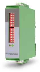
Features
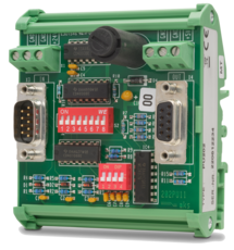
Pulse input in format A, /A, B, /B, Z, /Z [RS422, HTL]
Pulse input in format A, B, Z [HTL]
Input frequency up to 1 MHz
Pulse output in format A, /A, B, /B, Z, /Z [RS422, HTL]
Pulse output in format A, B, Z [HTL]
Power supply 9 ... 30 VDC
Settings via DIL switches
Level conversion (RS422, HTL single-ended, HTL differential, TTL and vice versa)
Division of two-track A / B pulses with adjustable ratio 1: 1 to 1: 4096
Division of the Z pulse with adjustable ratio 1: 1 to 1: 256
External HTL signals for various functions
Implementation between the two types of representations for the direction of rotation (A / B 90 °, A/B Dir and vice versa, Division possible)
Snap-on housing for top-hat rail (acc. EN 60715)
Dimension (B x H X T) 22,5 x 102 x 102 mm
Features
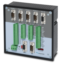
4 pulse inputs with format A, /A, B, /B [RS422]
4 scalable 12-bit analog inputs for ±10 V or 0/4 ... 20 mA
8 control inputs for PNP signals [10 ... 30 VDC]
4 scalable 12-bit analog outputs for ±10 V or 0/4 ... 20 mA
Short loop time (depending on application)
Power supply 18 ... 35 VDC
Snap-on housing for top-hat rail (according to EN 60715)
Setup via Windows operator software (free of charge)
OnBoard interfaces: RS232 and CANopen
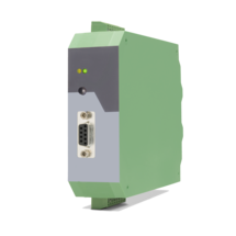
Features
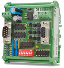
Pulse input with format A, B, Z [HTL] (10 ... 30 V)
Input frequency max. 200 kHz
Pulse output with format A, /A, B, /B, Z, /Z [RS422 / TTL]
Power supply 5 VDC
Converts HTL levels (A / B / Z) in TTL / RS422, incl. the inverted signals
Converts also static/separate directional information into a dual channel A / B signal with a 90° phase shift
Open print version with plastic snap-on housing for top-hat rail (according to EN 60715)
Features
Pulse input with format A, /A, B, /B, Z, /Z [TTL / RS422]
Input frequency max. 200 kHz
Pulse output with format A, B, Z [HTL]
Power supply 10 ... 30 VDC
Converts TTL / RS422 signals (A, /A, B, /B, Z, /Z) in HTL format with an output level of 10 ... 30 VDC
Generates additionally an A / B directional information with 90° phase shift‚ a static HIGH / LOW directional signal or separate directional pulses
Open print version with plastic snap-on housing for top-hat rail (according to EN 60715)
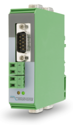
Features
1 pulse input with format A, B, Z [HTL] or A, /A, B, /B, Z, /Z [RS422]
Input frequency up to 500 kHz
1 pulse output with format A, /A, B, /B, Z, /Z [RS422, HTL]
Power supply 5 ... 30 VDC
Potential separation between input and output
Possibility to convert A, B / 90 ° directional information into static directional signal and vice versa
Connections on the input as well as on the output either via sub-D plugs or plug-in screw terminals (parallel connections)
Snap-on housing for top-hat rail (according to EN 60715)
Features
Encoder input with format SIN+, SIN-, COS+, COS-, REF+, REF- [1 Vss]
Control input „Error Release“ for PNP signals [10 ... 30 VDC]
Input frequency up to 400 kHz
Pulse output with format A, /A, B, /B, Z, /Z [RS422] or with format A, B, 90° [HTL]
Output frequency up to 4 MHz [RS422]
Control output „Error“ with push-pull characteristic, short-circuit-proof, [5 ... 30 VDC]
Power supply 18 ... 30 VDC
Snap-on housing for top-hat rail (according to EN 60715)
Adjustable multiplier for interpolation rates from 1:5 to 1:50
Adjustable divider 1:1 – 1:255 to reduce the output frequency
Features
1 encoder input with format SIN+, SIN-, COS+, COS-, REF+, REF- [1 Vss]
Maximum sinus input frequency 500 kHz with max. 200 ns conversion time
2 signal outputs with format SIN+, SIN-, COS+, COS-, REF+, REF- [1 Vss]
2 pulse outputs with format A, /A, B, /B, Z, /Z [RS422, TTL, HTL]
Power supply 17 ... 30 VDC
Snap-on housing for top-hat rail (according to EN 60715)
Features
1 encoder input with format SIN+, SIN-, COS+, COS-, REF+, REF- [1 Vss]
Maximum sinus input frequency 500 kHz with max. 200 ns conversion time
4 signal outputs with format SIN+, SIN-, COS+, COS-, REF+, REF- [1 Vss]
Power supply 17 ... 30 VDC
Snap-on housing for top-hat rail (according to EN 60715)
Features
Suitable for display units with front dimensions 96 x 48 mm
(fits not to Profibus indicator PB340)
Protection class IP65
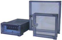
Features
To increase the protection class in dusty or wet environments, several types of protection caps are available for motrona units.
Some of the elastic and transparent plastic caps allow you to operate the keypad or to set the thumbwheel switches behind the cap, without removing it.
Page load link