Skip to content
Features
Up to 14 Bits of Single-Turn Resolution
SSI and CANopen Communications
58 mm Diameter
Durable Magnetic Technology
Retains Absolute Position After a Power Outage
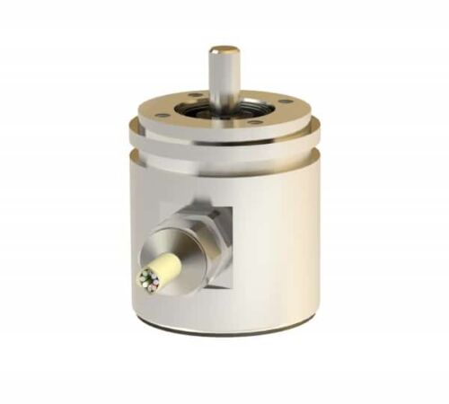
Features
Robust aluminium or stainless steel housing (wall thicknesses up to 5 mm)
Stainless steel shaft and ball bearing - ball bearing with Simmer ring
Rotor with shaft and permanent magnet mounted in pre-chamber
Sensor circuit consisting of ASIC
Hall elements and interface electronics in enclosed main chamber
Housing protection type IP 69K additionally cast
Electrical connection via cable (open cable ends)
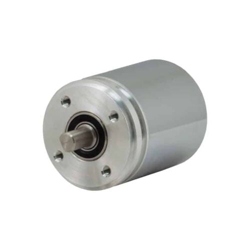
Features
Interface: SSI
Design: 42mm
Housing Material: Aluminium, stainless steel
Flange & Shaft: Synchroniser flange
Resolution: 4096 steps/360°<)
Code type: Binary, Gray (optional)
Electrical connection: Cable 1m
Electrical and/or mechanical variant: Basic version
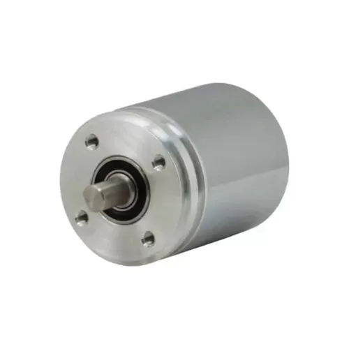
Features
Robust aluminium or stainless steel housing (wall thicknesses up to 5 mm)
Stainless steel shaft and ball bearing - ball bearing with Simmer ring
Rotor with shaft and permanent magnet mounted in pre-chamber
Sensor circuit consisting of ASIC
Hall elements and interface electronics in enclosed main chamber
Housing protection type IP 69K additionally cast
Electrical connection via cable (open cable ends)
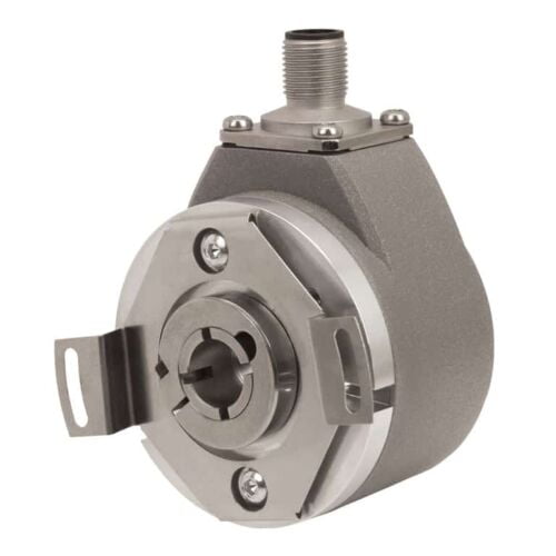
Features
Number of output pulses per revolution 18000-1800000 ppr
Line number on disc (z) 18000
Reference signal - standard: 1 per shaft revolution
- distance coded: 36 per shaft revolution
Permissible mech. speed ≤ 3000 rpm
Max. operating speed 600 to 1000 rpm
Accuracy grades ± 5.0 arc. sec
Permissible shaft runout - axial: 0.02 mm
- radial: ± 0.02 mm
Starting torque at 20°C ≤ 0.08 Nm
Rotor moment of inertia < 0.6x10⁻⁴ kgm2
Protection (IEC 529) IP64
Maximum weight without cable 1.2 kg
Operating temperature 0...+70°C
Storage temperature -30...+85°C
Maximum humidity (non-condensing) 98%
Permissible vibration (55 to 2000 Hz) ≤ 100 m/s²
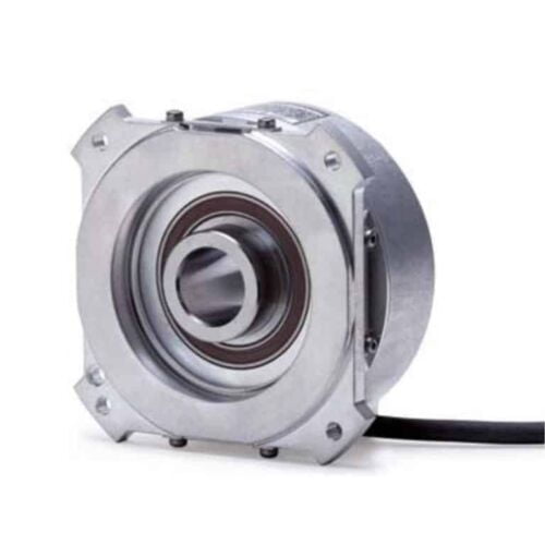
Features
Absolute measuring method
Hollow shaft diameter (up to 50 mm)
Integrated stator coupling
Simple installation
Typical field of application
Rotational axes with reduced accuracy requirements
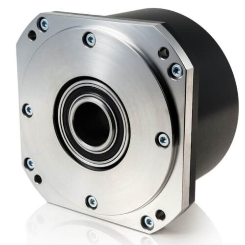
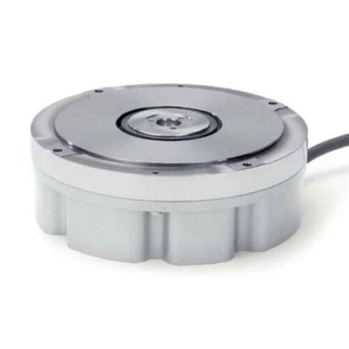
Features
Absolute measuring method
Large hollow shaft diameter (up to 100 mm)
Integrated stator coupling
Compact size for limited installation space
System accuracy includes the deviation caused by the shaft connection
Outstanding dynamic response
Simple installation
Typical field of application
Rotary tables
Swivel heads
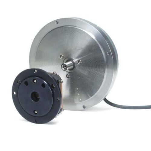
Features
Incremental measuring method
Solid shaft
Separate shaft coupling for large mounting tolerances
System accuracy does not include the deviation caused by the shaft connection
Typical field of application
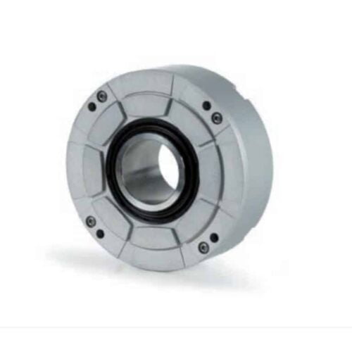
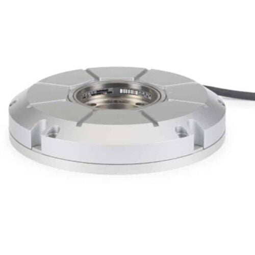
Features
Incremental measuring method
Large hollow shaft diameter (up to 60 mm)
Integrated stator coupling
Compact size for limited installation space
System accuracy includes the deviation caused by the shaft connection
Outstanding dynamic response
Simple installation
Typical field of application
Rotary tables
Swivel heads
Features
Large hollow shaft diameter (up to 10 m with a scale tape)
High shaft speeds up to 20,000 rpm
No additional starting torque from shaft seals
Segment versions
Also available with Functional Safety Modular angle encoders with optical scanning are available with various graduation carriers:
ERP/ERO: Glass circular scale with hub
ERA/ECA 4000: Steel drum
ERA 7000/8000: Steel scale tape
Typical field of application
High-resolution rotary axes with high reproducibility
Very high number of signal periods
Small mounting space
Small interpolation error and low signal noise
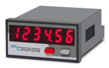
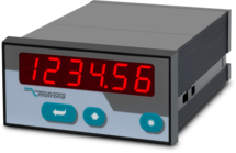
Features
Scalable 14-bit analog input for 0 ... 10 V or 0/4 ... 20 mA
Power supply 24 VDC
Miniature norm panel housing
5 digits LED display with 8 mm height
Display range -19999 ... 99999, adjustable zero and full-scale value
Latch input to freeze the display, minimum/maximum record memory
Easy to set up with only two front keys and menu support
Delivery includes adapter frame for 50 x 25 mm cut out and label set with dimensions
Front dimension 48 x 24 x 59 mm (1.89 x 0.945 x 2.322")
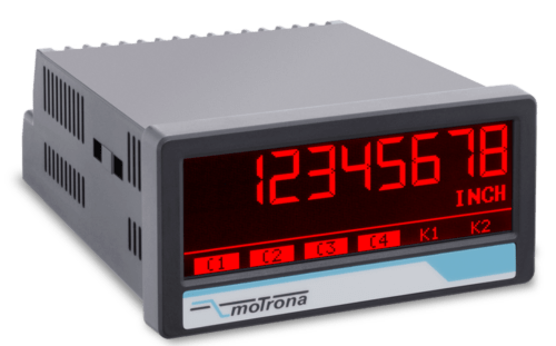
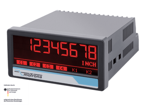
Features
2 universal 16-bit analogue inputs for ±10 V or 0/4 … 20 mA
3 control inputs for HTL / PNP signals
Power supply 18 ... 30 VDC
24 V auxiliary output for encoder supply
High accuracy reference output 10 V for potentiometers > 1 kOhm
3.78 x 1.89-inch norm panel housing and IP65 protection
Bright and high-contrast display with event-dependent color variations
Emulation of a 7-segment display inclusively icons and units
Intuitive and easy parameterization by plain text and touchscreen
Operating modes for visualization of INPUT 1, INPUT 2 or combinations of IN1 + IN2, IN1 - IN2, IN1 x IN2, IN1: IN2
Numerous features, e. g. tara, filters, averaging
Linearization with 24 control points
Options
Option AC: Power supply 115 ... 230 VAC
Option AO: 16-bit analog output, 4 control outputs, serial RS232 interface
Option AR: 16-bit analog output, 4 control outputs, serial RS485 interface
Option CO: 4 control outputs, serial RS232 interface
Option CR: 4 control outputs, serial RS485 interface
Option RL: 2 relay outputs
Option IO: IO-Link Device V1.1
Features
2 universal 16-bit analog inputs for ±10 V or 0/4 … 20 mA
3 control inputs for HTL / PNP signals
Power supply 18 ... 30 VDC
24 V auxiliary output for encoder supply
High accuracy reference output 10 V for potentiometers > 1 kOhm
3.78 x 1.89-inch norm panel housing and IP65 protection
Bright and high-contrast display with event-dependent color variations
Emulation of a 7-segment display inclusively icons and units
Intuitive and easy parameterization by plain text and touchscreen
Operating modes for visualization of INPUT 1, INPUT 2 or combinations of IN1 + IN2, IN1 - IN2, IN1 x IN2, IN1: IN2
Numerous features, e. g. Ttara, filters, averaging
Linearization with 24 control points
Option IO (= IO-Link Device)
Data transfer via COM3 (230,4 kBaud)
Cycle times < 3 msec
Process data IN 32 Byte (6 x process values from AX350):
- Analog value 1 (scaled / linearized) and unit
- Analog value 2 (scaled / linearized) and unit
- Analog value 1 (scaled / linearized) with totalisation and unit
- Analog value 2 (scaled / linearized) with totalisation and unit
- Shortcut analogue value 1 (scaled / linearized) with analogue value 2 (scaled / linearized) and unit
- Shortcut totalisator analogue value 1 (scaled / linearized) with totalisator analogue value 2 (scaled / linearized) and unit
Process data Out 8 Byte (2 x IO-Link process values to AX350):
- IOL process value Out 1 with scaling, adjustable decimal point and programmable units
- IOL process values Out 2 with scaling, adjustable decimal point and programmable units
Combinable with further options:
Option AC: Power supply 115 ... 230 VAC
Option AO: 16-bit analog output, 4 control outputs, serial RS232 interface
Option AR: 16-bit analog output, 4 control outputs, serial RS485 interface
Option CO: 4 control outputs, serial RS232 interface
Option CR: 4 control outputs, serial RS485 interface
Option RL: 2 relay outputs
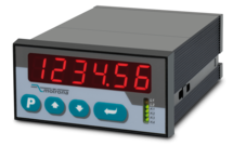
Features
Simple specification of individual setpoints and display of individual setpoints or actual values
Also suitable as a parallel remote display for all devices with a serial interface
Basic function: display, edit, configure
6 digits LED display with 15 mm height
Power supply 16 ... 35 VDC
Compact norm panel housing
Dimension 96 x 48 x 141 mm
Features
2 pulse inputs with format A, B, 90° [HTL] or A, /A, B, /B [RS422]
4 control inputs for HTL / PNP / NPN / Namur signals [10 ... 30 VDC]
Input frequency up to 300 kHz
4 fast transistor outputs, push-pull, short-circuit-proof [5 … 30 VDC]
1 scalable 14-bit analog output (±10 V or 0/4 … 20 mA)
Loop time approx. 250 µs
Power supply 24 VAC and 17 … 40 VDC
Compact norm panel housing (according to EN 60715)
Top hat rail mounting by using SM300 support brackets (option)
Setup via keys or via PC by serial RS232 interface
PROFIBUS connection via Motrona gateway PB251
Features
2 pulse inputs with format A, B, 90° [HTL] or A, /A, B, /B [RS422]
4 control inputs for HTL / PNP / NPN / Namur signals [10 ... 30 VDC]
Input frequency up to 300 kHz
4 fast transistor outputs, push-pull, short-circuit-proof [5 … 30 VDC]
4 potential-free changeover relay outputs
1 scalable 14-bit analog output (±10 V or 0/4 … 20 mA)
Loop time approx. 250 µs
Power supply 24 VAC and 17 … 40 VDC
Compact norm panel housing (according to EN 60715)
Top hat rail mounting by using SM600 support brackets (option)
Setup via keys or via PC by serial RS232 interface
PROFIBUS connection via Motrona gateway PB251
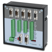
Features
MC700 is a universal motion controller for 1 to 4 axes, which can be assigned any motion control functions by loading firmware. Together with the firmware BY701 (see firmware), this controller offers excellent synchronous functions for 1 - 4 axes.The firmware offers all conceivable possibilities for the synchronization of drives, including the influence of phase position and the relative position between the drives and numerous index and print mark functions.
Optionally, a "physical master" or the built-in "virtual master axis" with programmable speeds and ramps can be used as the master drive.
The number of successive axes can be extended arbitrarily via a cascading output.
MC700 controllers can be operated via an external control terminal, serial interface or optional via CANBUS (MC700/CI). PC operator software is included.
PROFIBUS connection possible via gateway PB251 (see accessories)
Features
Power supply 10 ... 30 VDC
Compact norm panel housing
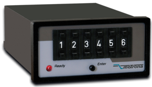
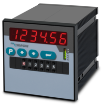
Preset range: 6 digits or 5 digits with sign
DIL-switch for set up of the transmission parameters
Dimension H x B x T = 96 x 48 x 140 mm (3.78 x 1.89 x 5.51 ")
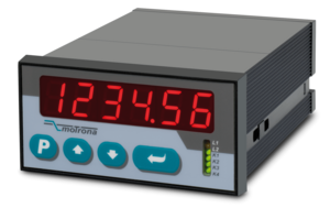
Features
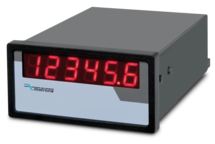
Power supply 10 ... 30 VDC
Compact norm panel housing
6 digits LED display with 15 mm height
Display range -199999 ... 999999
DIL-switch for setup of the transmission parameters
Dimension H x B x T = 96 x 48 x 140 mm (3.78 x 1.89 x 5.12 ")
Features
Processor:
Siemens C515C operating at 10 MHz
Power supply:
Using internal power of the motion controller
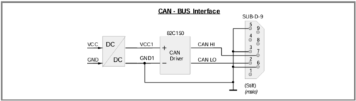
CAN Communication:
DIN ISO 11898
CANopen (CiA DS301)
Baud rates:
10, 20, 50, 125, 250, 500, 1000 kBit/s (adjustable)
Features
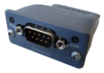
Internal power supply 3,3 V
Ambient temperature 0° C ... +60° C / 32° F ... 140° F (operating), -40° C ... +70° C / -40° F ... 158° F (storage)
10, 20, 50, 100, 125, 250, 500, 800 und 1000 kbps Baud rates
SUB-D-9-pin male, galvanically isolated
Features
USB to RS232 converter (compatible with all existing Windows versions)
Serial RS232 cable (for connection between the converter and motrona unit)
One connector Sub-D-9 (male)
One connector Sub-D-9 (female)
Length 3 m (approx. 10 feet)
Windows driver CD enclosed
Features
2 pulse inputs with format A, B, 90° [HTL] or A, /A, B, /B [RS422]
4 control inputs for HTL / PNP / NPN / Namur signals [10 ... 30 VDC]
Input frequency up to 300 kHz
4 fast transistor outputs, push-pull, short-circuit-proof [5 … 30 VDC]
1 scalable 14-bit analog output (±10 V or 0/4 … 20 mA)
Loop time approx. 250 µs
Cutting length specification via keyboard Power supply 24 VAC and 17 … 40 VDC
Compact norm panel housing (according to EN 60715)
Top hat rail mounting by using SM300 support brackets (option)
Setup via keys or via PC by serial RS232 interface
PROFIBUS connection via Motrona gateway PB251
Features
2 pulse inputs with format A, B, 90° [HTL] or A, /A, B, /B [RS422]
4 control inputs for HTL / PNP / NPN / Namur signals [10 ... 30 VDC]
Input frequency up to 300 kHz
4 fast transistor outputs, push-pull, short-circuit-proof [5 … 30 VDC]
4 potential-free changeover relay outputs
1 scalable 14-bit analog output (±10 V or 0/4 … 20 mA)
Loop time approx. 250 µs
Cutting length specification via BCD decade switch on the front
Power supply 24 VAC and 17 … 40 VDC
Compact norm panel housing (according to EN 60715)
Top hat rail mounting by using SM600 support brackets (option)
Setup via keys or via PC by serial RS232 interface
PROFIBUS connection via Motrona gateway PB251
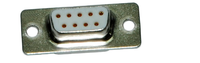
Features
Solder connection
Metallised plastic enclosure
Mounting screws included
Page load link