Skip to content
Features
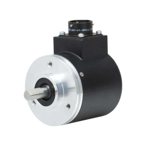
Standard Size 25 package (2.5")
Resolutions up to 12-bit (4096 counts)
Incorporates Opto-ASIC technology
Industrial-grade, heavy-duty housing
Optional IP67 seal
Features
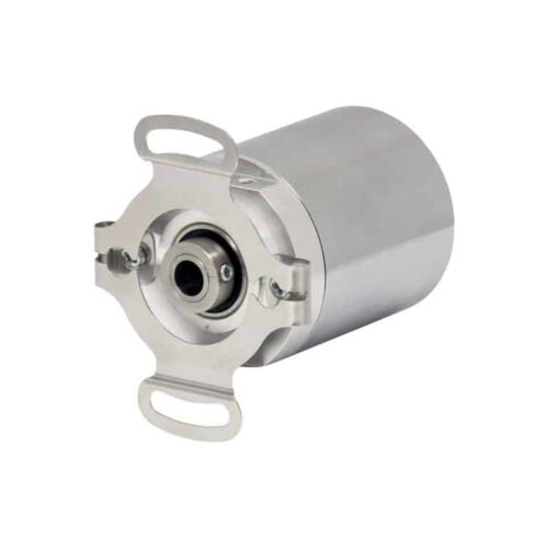
Low profile—40mm
Thru-bore or hollow-bore styles
Industrial-grade, heavy-duty housing
State-of-the-art Opto-ASIC circuitry
Features
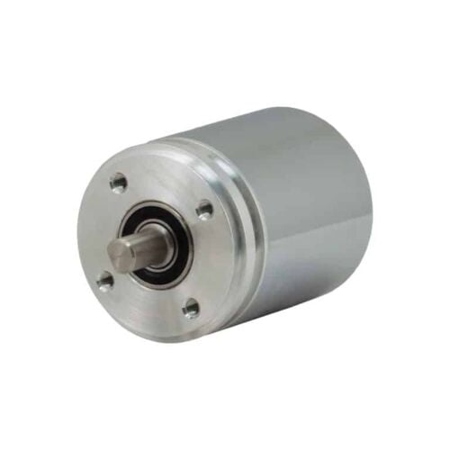
Standard Size 36mm package (1.42")
Durable magnetic technology
Multiturn absolute encoder (12-bit/39-bit)
SSI and CANopen communications
Proven new turns counting technology — no gears or batteries
Features
Standard Size 36mm package (1.42")
Durable magnetic technology
Multiturn absolute encoder (12-bit/39-bit)
SSI and CANopen communications
Proven new turns counting technology — no gears or batteries
Features
Multi-Turn Absolute Encoder (14 Bit/39 Bit)
SSI and CANopen Communications
58 mm Diameter
Durable Magnetic Technology
Proven Turns Counting Technology – No Gears or Batteries
Retains Absolute Position After a Power Outage
Features
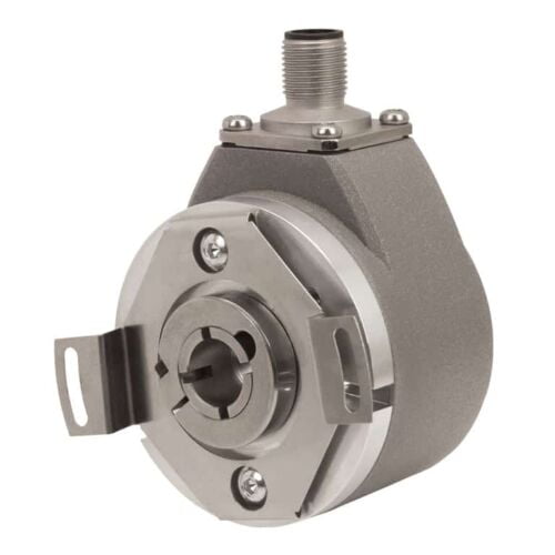
Standard Size 36mm package
Durable magnetic technology
Up to 14 bits of single-turn resolution
SSI and CANopen communications
Proven turns counting technology—no gears or batteries
Flex mount eliminates couplings and is ideal for motors or shafts
Features
Standard size 36 mm package (1.42")
Durable magnetic technology
Up to 14 bits of single-turn resolution
SSI and CANopen communications
Proven new turns counting technology — no gears or batteries
Features
Up to 14 Bits of Single-Turn Resolution
SSI and CANopen Communications
58 mm Diameter
Durable Magnetic Technology
Retains Absolute Position After a Power Outage
Features
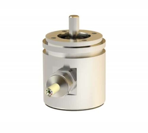
Robust aluminium or stainless steel housing (wall thicknesses up to 5 mm)
Stainless steel shaft and ball bearing - ball bearing with Simmer ring
Rotor with shaft and permanent magnet mounted in pre-chamber
Sensor circuit consisting of ASIC
Hall elements and interface electronics in enclosed main chamber
Housing protection type IP 69K additionally cast
Electrical connection via cable (open cable ends)
Features
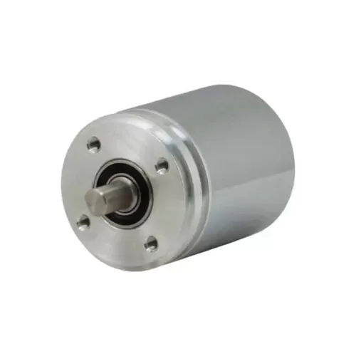
Interface: SSI
Design: 42mm
Housing Material: Aluminium, stainless steel
Flange & Shaft: Synchroniser flange
Resolution: 4096 steps/360°<)
Code type: Binary, Gray (optional)
Electrical connection: Cable 1m
Electrical and/or mechanical variant: Basic version
Features
Robust aluminium or stainless steel housing (wall thicknesses up to 5 mm)
Stainless steel shaft and ball bearing - ball bearing with Simmer ring
Rotor with shaft and permanent magnet mounted in pre-chamber
Sensor circuit consisting of ASIC
Hall elements and interface electronics in enclosed main chamber
Housing protection type IP 69K additionally cast
Electrical connection via cable (open cable ends)
Features
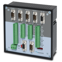
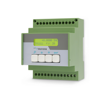
MC700 is a universal motion controller for 1 to 4 axes, which can be assigned any motion control functions by loading firmware. Together with the firmware BY701 (see firmware), this controller offers excellent synchronous functions for 1 - 4 axes.The firmware offers all conceivable possibilities for the synchronization of drives, including the influence of phase position and the relative position between the drives and numerous index and print mark functions.
Optionally, a "physical master" or the built-in "virtual master axis" with programmable speeds and ramps can be used as the master drive.
The number of successive axes can be extended arbitrarily via a cascading output.
MC700 controllers can be operated via an external control terminal, serial interface or optional via CANBUS (MC700/CI). PC operator software is included.
PROFIBUS connection possible via gateway PB251 (see accessories)
Features
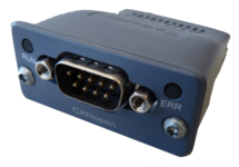
Internal power supply 3,3 V
Ambient temperature 0° C ... +60° C / 32° F ... 140° F (operating), -40° C ... +70° C / -40° F ... 158° F (storage)
10, 20, 50, 100, 125, 250, 500, 800 und 1000 kbps Baud rates
SUB-D-9-pin male, galvanically isolated
Features
USB to RS232 converter (compatible with all existing Windows versions)
Serial RS232 cable (for connection between the converter and motrona unit)
One connector Sub-D-9 (male)
One connector Sub-D-9 (female)
Length 3 m (approx. 10 feet)
Windows driver CD enclosed
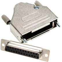
Features
Solder connection
Metallised plastic enclosure
Mounting screws included
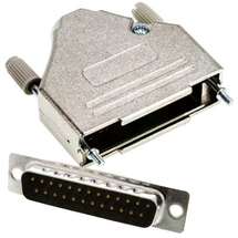
Features
Solder connection
Metallised plastic enclosure
Mounting screws included
Features
Solder connection
Metallised plastic enclosure
Mounting screws included
Features
Solder connection
Metallised plastic enclosure
Mounting screws included
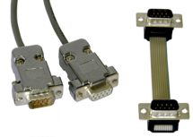
Features
Sub-D-9 connectors (male) on both sides
cable length 10 cm (approx. 3.4")
Features
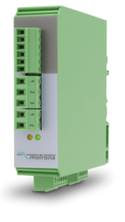
Pulse input with format A, B, Z [HTL single-ended, TTL single-ended] or A, /A, B, /B, Z, /Z [RS422, HTL differential]
4 control inputs for HTL, PNP signals [10 ... 30 VDC]
Input and output frequency up to 1 MHz
3 incremental outputs with format A, /A, B, /B, Z, /Z, Push-Pull, [8 … 29 VDC]
Power supply 9 ... 30 VDC
Snap-on housing for top-hat rail (acc. EN 60715)
Multiplier/divisor adjustable as quotient F1 / F2
Multiplication/division without cumulative residual errors
Additional functions such as jog, trim, offset and reference
Features
Pulse input with format A, B, 90° [HTL] or A, /A, B, /B, Z, /Z [RS422]
4 control inputs for PNP signals [10 ... 30 VDC]
Input and output frequency up to 1 MHz
Pulse output with format A, /A, B, /B, Z, /Z and
push-pull characteristic, [5 ... 30 VDC]
Power supply 11 ... 30 VDC
Snap-on housing for top-hat rail (according to EN 60715)
LCD backlighted
Setup via keys, RS232
The device multiplies an incoming frequency by a proportional factor F1 and a reciprocal factor F2. The two factors F1 and F2 are adjustable in the range of 0.0005 to 9.9999
All operation modes provide error-free frequency conversion, with full consideration of the A / B phase and direction of the quadrature signals, therefore no cumulative errors, even with continuous changes of directions and vibrations
Zero pulse generator: the frequency multiplier generates at the output an index signal with an adjustable pulse interval, which can be synchronized as needed with the zero pulse at the input
Features
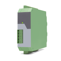
Control input with format [HTL]
2 SSI inputs with format [RS422]
Cutt-off frequency 100 kHz ... 1 MHz
2 encoder inputs, short-circuit-proof
1 SSI output with format [RS422]
Power supply 12 ... 30 V DC
Current consumption (unloaded) 50 mA
Encoder supply 2 x 125mA (Vin – 2 V) short-circuit-proof
Delay / Output / Input100 ns
Operation temperature : 0 ... 45 °C (32 ... 113 °F)
SSI pause time min. 25 ns
Switching time is synchronized automatically with the next SSI break
Cascadable for more SSI encoders
All connections via pluggable screw terminal block
Snap-on housing for top-hat rail (according to EN 60715)
LEDs for indication of the input pulses
Dimension W x H x D = 22,5 x 121 x 112 mm (8.86 x 47.64 x 44.09'')
Plastic housing incl. plug
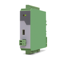
Features
4 analog inputs for ±10 V or 0/4 ... 20 mA (2x current / 2x voltage)
optionally 3 control inputs for PNP signals [10 ... 30 VDC]
IO link interface
Power supply 12 ... 30 VDC
Compact housing for mounting on 35 mm DIN rail (according to EN 60715)
Features
1 SSI input (10 … 32 bit)
for single-turn and multiturn encoders
optionally 3 control inputs for PNP signals [10 ... 30 VDC]
IO link interface
Power supply 12 ... 30 VDC
Compact housing for mounting on 35 mm DIN rail (according to EN 60715)
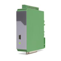
Features
SSI input with format DATA+, DATA-, CLOCK+, CLOCK- up to 32 Bit
Impulse inputs A, B [HTL], A, /A, B, /B [RS422, HTL]
3 control inputs (Hold) for PNP signals [10 ... 30 VDC]
Start-stop interface for absolute transducers and magnetostrictive sensors
Input frequency up to 1 MHz
25-bit parallel output push-pull in BCD, binary or Gray code format
Power supply 18 ... 30 VDC
Compact housing for mounting on 35 mm top-hat rail (according to EN 60715)
Page load link