Skip to content
Features
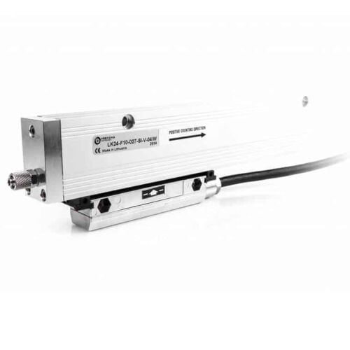
Type: Incremental encoder
Measuring length: 3.240 mm to 30.040 mm
Grating period: 40 µm
Accuracy: Up to ±10 µm within the measuring length
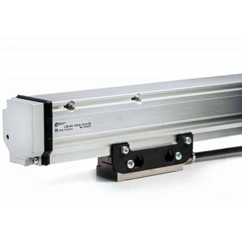
Features
Type: Photoelectric absolute linear encoder (measures absolute position)
Measuring length: Up to 3.240 mm (customizable)
Interface: SSI or BiSS serial interface for digital communication
Accuracy: Up to ±1 µm high accuracy
Optional incremental track: Provides 1Vpp incremental signal for applications requiring both absolute and incremental position data.
Features
Standard Size 36mm package (1.42")
Durable magnetic technology
Multiturn absolute encoder (12-bit/39-bit)
SSI and CANopen communications
Proven new turns counting technology — no gears or batteries
Features
Standard Size 36mm package (1.42")
Durable magnetic technology
Multiturn absolute encoder (12-bit/39-bit)
SSI and CANopen communications
Proven new turns counting technology — no gears or batteries
Features
Multi-Turn Absolute Encoder (14 Bit/39 Bit)
SSI and CANopen Communications
58 mm Diameter
Durable Magnetic Technology
Proven Turns Counting Technology – No Gears or Batteries
Retains Absolute Position After a Power Outage
Features
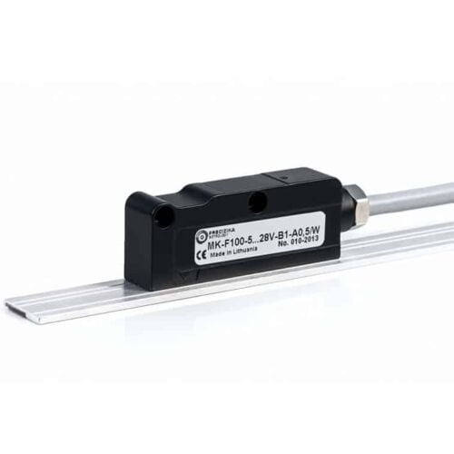
Magnetic absolute linear encoder
MK has a measuring length of up to 50.000 mm
Accuracy can reach up to ±35 μm.
Encoder has two versions of serial interface - SSI or BiSS C
Optionally it can have 2 analog sinusoidal signals with phase shift 90°C and amplitude approx. 1Vpp.
Features
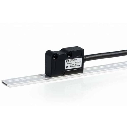
Measuring length: Up to 50,000 mm (50 meters)
Accuracy: Up to ±25 micrometres (μm)
Customizable: Other parameters can be modified to meet specific needs
Features
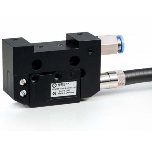
Converts the movement of key machine parts into electrical signals.
Designed for harsh industrial environments and resistant to various physical and environmental factors.
Magnetic band length can reach up to 50 meters.
Allows for either user-defined reference marks or external zero signal actuator.
LED on the reading head confirms reference mark detection.
Compressed air can be used to clean the rail surface, improving accuracy.
Two output signal options:
PCMT-F: Square-wave with built-in interpolation electronics.
PCMT-AV: Sinusoidal signal requiring external interpolation.
Features
Standard Size 36mm package
Durable magnetic technology
Up to 14 bits of single-turn resolution
SSI and CANopen communications
Proven turns counting technology—no gears or batteries
Flex mount eliminates couplings and is ideal for motors or shafts
Features
Standard size 36 mm package (1.42")
Durable magnetic technology
Up to 14 bits of single-turn resolution
SSI and CANopen communications
Proven new turns counting technology — no gears or batteries
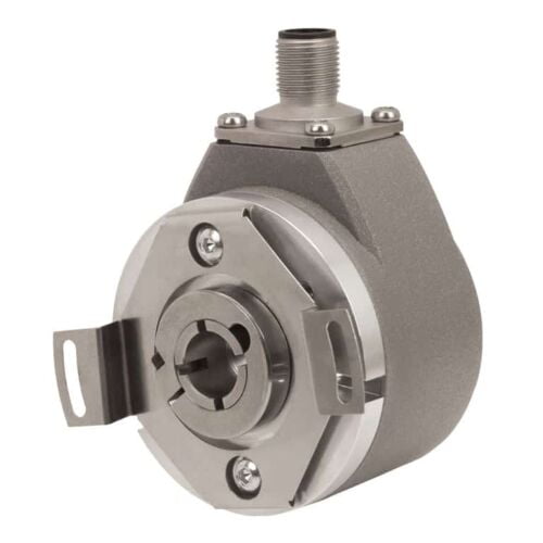
Features
Up to 14 Bits of Single-Turn Resolution
SSI and CANopen Communications
58 mm Diameter
Durable Magnetic Technology
Retains Absolute Position After a Power Outage
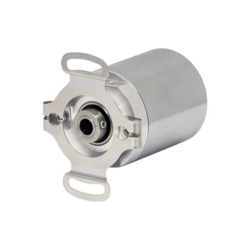
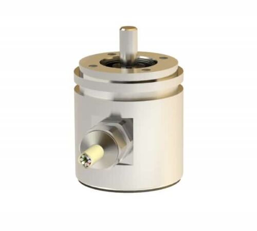
Features
Robust aluminium or stainless steel housing (wall thicknesses up to 5 mm)
Stainless steel shaft and ball bearing - ball bearing with Simmer ring
Rotor with shaft and permanent magnet mounted in pre-chamber
Sensor circuit consisting of ASIC
Hall elements and interface electronics in enclosed main chamber
Housing protection type IP 69K additionally cast
Electrical connection via cable (open cable ends)
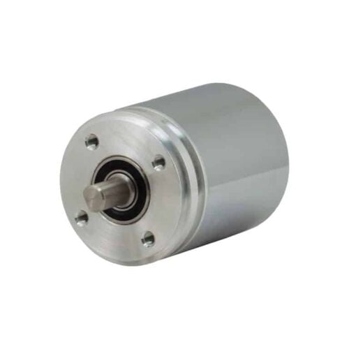
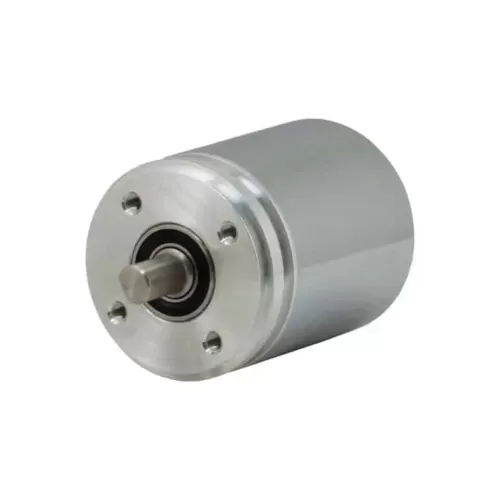
Features
Interface: SSI
Design: 42mm
Housing Material: Aluminium, stainless steel
Flange & Shaft: Synchroniser flange
Resolution: 4096 steps/360°<)
Code type: Binary, Gray (optional)
Electrical connection: Cable 1m
Electrical and/or mechanical variant: Basic version
Features
Robust aluminium or stainless steel housing (wall thicknesses up to 5 mm)
Stainless steel shaft and ball bearing - ball bearing with Simmer ring
Rotor with shaft and permanent magnet mounted in pre-chamber
Sensor circuit consisting of ASIC
Hall elements and interface electronics in enclosed main chamber
Housing protection type IP 69K additionally cast
Electrical connection via cable (open cable ends)
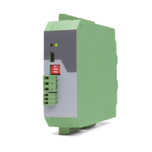
Features
6-wire connection for one strain gauge full bridge sensor
4 control inputs [HTL/PNP]
1 analog output ±10 V, 0/4 ... 20 mA, 16 bit
4 control outputs for signalling different operation states
Power supply 18 ... 30 VDC
Functions for scaling and linking the sensor signals (e.g. A+B, A-B, ...)
Adjustable bridge voltage per sensor from 3 VDC ... 10 VDC
Sensitivity of the sensor inputs 1 ... 10 mV
Transmission of the sensor data via RS485
Programming via USB and the user interface OS (freeware)
Protection class IP20
Compact housing for mounting on 35 mm top-hat rail (according to EN 60715)
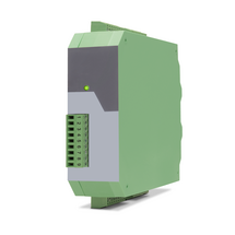
Features
6-wire connection for two independent strain gauge full bridge sensors
4 control inputs [HTL/PNP]
2 independent analog outputs ±10 V, 0/4 ... 20 mA, 16 bit
4 control outputs for signalling different operation states
Power supply 18 ... 30 VDC
Functions for scaling and linking the sensor signals (e.g. A+B, A-B, ...)
Adjustable bridge voltage per sensor from 3 VDC ... 10 VDC
Sensitivity of the sensor inputs 1 ... 10 mV
Transmission of the sensor data via RS485
Programming via USB and the user interface OS (freeware)
Protection class IP20
Compact housing for mounting on 35 mm top-hat rail (according to EN 60715)
Features
4 analog inputs for ±10 V or 0/4 ... 20 mA (2x current / 2x voltage)
optionally 3 control inputs for PNP signals [10 ... 30 VDC]
IO link interface
Power supply 12 ... 30 VDC
Compact housing for mounting on 35 mm DIN rail (according to EN 60715)
Features
1 Strain gauge input
3 VDC and 10 VDC bridge voltage per sensor connection
1 … 10 mV sensitivity
optionally 3 control inputs for PNP signals [10 ... 30 VDC]
IO link interface
Power supply 12 ... 30 VDC
Compact housing for mounting on 35 mm DIN rail (according to EN 60715)
Features
4 independent input channels with format A, B, C, D [HTL] or A, /A, B, /B, C, /C, D, /D [RS422], also possible for single-channel
4 output channels with format A, B, C, D [HTL] or A, /A, B, /B, C, /C, D, /D [RS422]
Maximum input frequency 1 MHz
Very short conversion time < 300 ns
Optical wavelength 1300 nm
Transmission distance up to 3000 meters
Power supply 5 VDC (for LW213)
Power supply 10 ... 30 VDC (for LW213-1, LW213-2, LW213-3)
Snap-on housing for top-hat rail (according to EN 60715)
Pre-configured optical fibres are available
Features
4 independent input channels with format A, B, C, D [HTL] or A, /A, B, /B, C, /C, D, /D [RS422], also possible for single channel
4 output channels with format A, B, C, D [HTL] or A, /A, B, /B, C, /C, D, /D [RS422]
Maximum input frequency 1 MHz
Very short conversion time < 300 ns
Optical wavelength 1300 nm
Transmission distances up to 3000 meters
Power supply 5 VDC (for LW214)
Power supply 10 ... 30 VDC (for LW214-1, LW214-2)
Snap-on housing for top-hat rail (according to EN 60715)
Pre-configured optical fibers are available
Features
4 independent input channels with format A, B, C, D [HTL] or A, /A, B, /B, C, /C, D, /D [RS422], also possible for single channel
4 output channels with format A, B, C, D [HTL] or A, /A, B, /B, C, /C, D, /D [RS422]
Maximum input frequency 1 MHz
Very short conversion time < 300 ns
Optical wavelength 850 nm
Transmission distance up to 2000 meters
Power supply 5 VDC (for LW215)
Power supply 10 ... 30 VDC (for LW215-1, LW215-2, LW216-3)
Snap-on housing for top-hat rail (according to EN 60715)
Pre-configured optical fibers are available
Features
4 independent input channels with format A, B, C, D [HTL] or A, /A, B, /B, C, /C, D, /D [RS422], also possible for single channel
4 output channels with format A, B, C, D [HTL] or A, /A, B, /B, C, /C, D, /D [RS422]
Maximum input frequency 1 MHz
Very short conversion time < 300 ns
Optical wavelength 850 nm
Transmission distance up to 2000 meters
Power supply 5 VDC (for LW216)
Power supply 10 ... 30 VDC (for LW216-1, LW216-2)
Snap-on housing for top-hat rail (according to EN 60715)
Pre-configured optical fibers are available
Features
1 SSI input / output channel [RS422] with format DATA+, DATA-, CLOCK+, CLOCK-
1 Error input (LW217) resp. 1 open-drain-output (LW218)
Maximum input frequency 1 MHz
Very short conversion time < 300 nsec.
Optical wavelength 850 nm
Transmission distance up to 2000 meters
Power supply 5 VDC (for LW217)
Power supply 10 ... 30 VDC (for LW217-1)
Free adjustable SSI resolution from 1 ... 99 bit
Snap-on housing for top-hat rail (according to EN 60715)
Pre-configured optical fibres are available
Features
1 SSI input / output channel [RS422] with format DATA+, DATA-, CLOCK+, CLOCK-
1 open-drain-output (LW218)
Maximum input frequency 1 MHz
Very short conversion time < 300 ns
Optical wavelength 1300 nm
Transmission distance up to 2000 meters
Power supply 5 VDC (for LW218)
Power supply 10 ... 30 VDC (for LW218-1)
Free adjustable SSI resolution from 1 ... 99 bit
Snap-on housing for top-hat rail (according to EN 60715)
Glass fibre cables are available ready-assembled
Features
Scalable 14 bit analog input for ±10 V or 0/4 ... 20 mA
4 control inputs for PNP signals [10 ... 30 VDC]
Pulse output with format A, B, 90° [HTL] or A, /A, B, /B, Z, /Z [RS422]
SSI output with format DATA+, DATA-, CLOCK+, CLOCK- up to 25 bit
Power supply 12 ... 30 VDC
Snap-on housing for top-hat rail (according to EN 60715)
Various user modes: Programmable V / f characteristics, programmable curves with optionally repeating curve cycles, additional control functions similar to a “motorized potentiometer”
USB, RS232 and RS485 interface for programming and serial readout of the conversion result and other internal registers
Adjustable filter functions as well as operator programmable linearization curves
Printer mode for automatic data transfer of internal registers to a data logger or PC
Page load link