Skip to content
Features
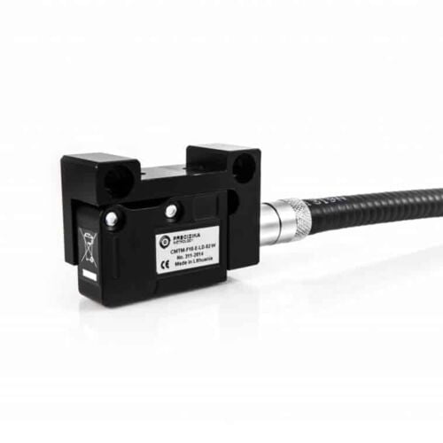
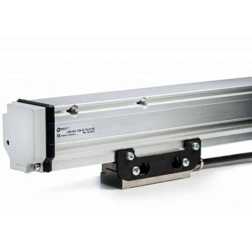
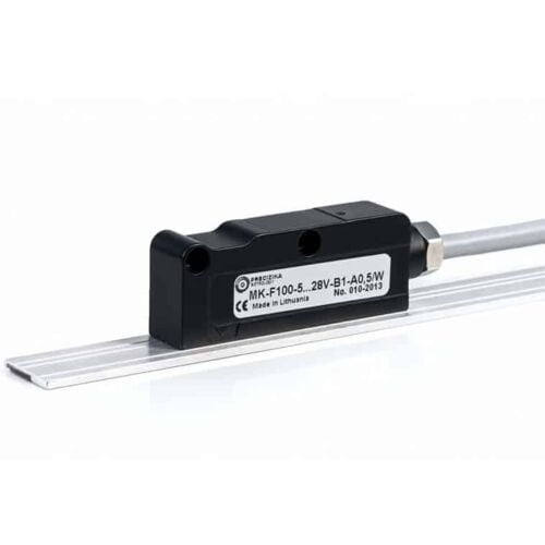
Type: Non-contact magnetic linear encoder (measures displacement without physical contact)
Measuring length: Up to 50 meters
Function: Converts linear movements of machine components into electrical signals with information about:
Value: Distance travelled
Direction: Forward or backward movement
Durability: Designed for harsh industrial environments and resistant to various contaminants and physical impacts.
Components:
Metal-based magnetic band (MP): Stores the encoded information
Reading head: Detects the magnetic field variations on the band and converts them into electrical signals
Profile rail (PS) with protective band: Provides mounting and protects the reading head
Features
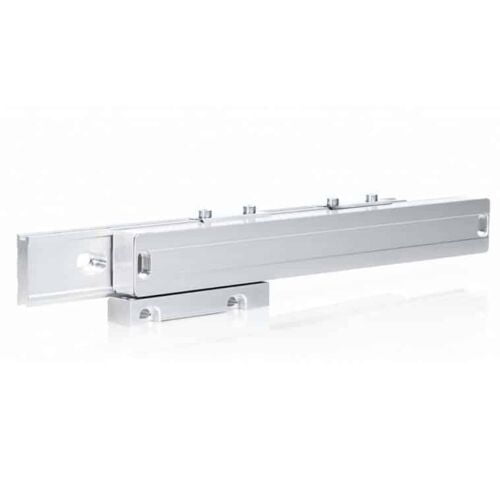
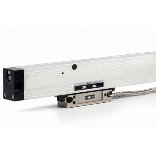
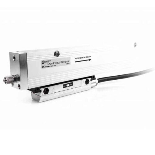
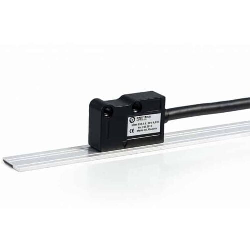
Type: Photoelectric linear displacement measuring device (measures changes in position)
Measuring length: Up to 2.040 mm
Grating period: Two options available: ±20 µm or ±40 µm (determines the smallest detectable movement)
Accuracy: Up to ±3 µm (indicates the encoder's closeness to the actual displacement)
Features
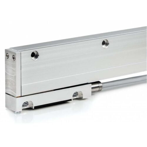
Measuring length: Up to 3.240 mm
Accuracy: Up to ±5 µm within any meter of its measuring length
Grating periods: Available in two options: ±20 µm and ±40 µm
Features
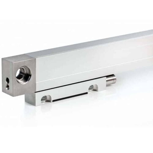
Similar to the L18 series: Shares most functionalities and specifications with the L18 series encoders.
Different housing fixation: Requires distinct mounting methods compared to the L18 series.
Improved thermal behaviour: More stable performance under different temperatures.
Features
Type: Photoelectric modular linear encoder
Measuring length:
Up to 20,000 mm (20 meters)
Can be even longer with special order
Accuracy: Up to ±3 µm
Features
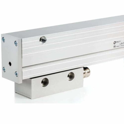
Type: Incremental linear displacement measuring device (measures changes in position)
Measuring length: Up to 3.240 mm
Accuracy: Up to ±3 µm within any meter of its measuring length (accuracy scales with length)
Vibration resistance: More resistant to vibrations than the L18 series encoders
Features
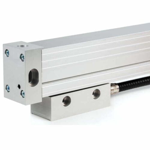
Similar to the L35 series: Shares most functionalities and specifications with the L35 series encoders.
Different mounting parameters: Requires distinct mounting methods compared to the L35 series.
Measuring length: Up to 3.240 mm.
Enhanced vibration resistance: More resistant to vibrations than the L18 series encoders, making it suitable for applications with higher vibration levels.
Features
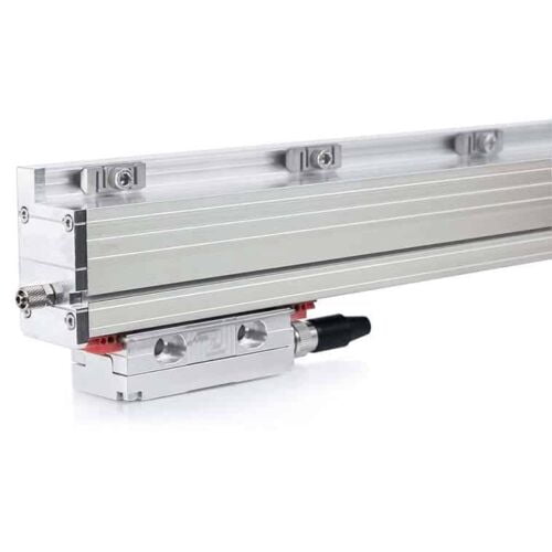
Type: Incremental encoder
Thermal behaviour: Reproducible, indicating stability under temperature changes
Reading head: Reversible for flexibility in installation
Measuring length: Up to 3.240 mm
Accuracy: Up to ±3 µm within the measuring length
Features
Type: Incremental encoder
Measuring length: 3.240 mm to 30.040 mm
Grating period: 40 µm
Accuracy: Up to ±10 µm within the measuring length
Features
Type: Photoelectric absolute linear encoder (measures absolute position)
Measuring length: Up to 3.240 mm (customizable)
Interface: SSI or BiSS serial interface for digital communication
Accuracy: Up to ±1 µm high accuracy
Optional incremental track: Provides 1Vpp incremental signal for applications requiring both absolute and incremental position data.
Features
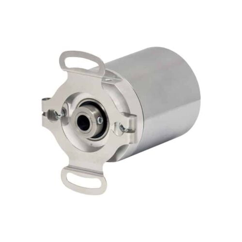
Standard Size 36mm package (1.42")
Durable magnetic technology
Multiturn absolute encoder (12-bit/39-bit)
SSI and CANopen communications
Proven new turns counting technology — no gears or batteries
Features
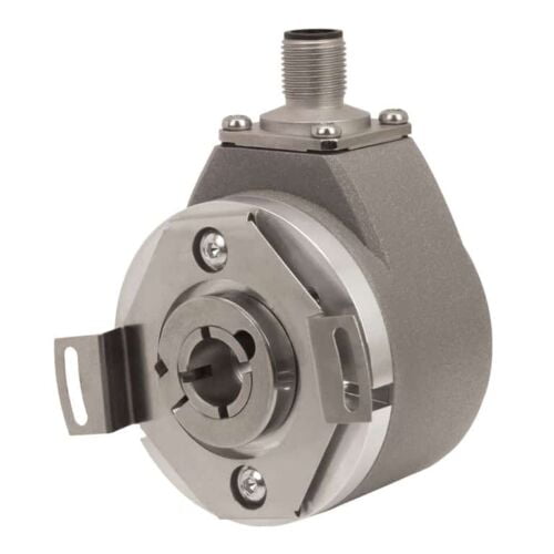
Multi-Turn Absolute Encoder (14 Bit/39 Bit)
SSI and CANopen Communications
58 mm Diameter
Durable Magnetic Technology
Proven Turns Counting Technology – No Gears or Batteries
Retains Absolute Position After a Power Outage
Features
Magnetic absolute linear encoder
MK has a measuring length of up to 50.000 mm
Accuracy can reach up to ±35 μm.
Encoder has two versions of serial interface - SSI or BiSS C
Optionally it can have 2 analog sinusoidal signals with phase shift 90°C and amplitude approx. 1Vpp.
Features
Measuring length: Up to 50,000 mm (50 meters)
Accuracy: Up to ±25 micrometres (μm)
Customizable: Other parameters can be modified to meet specific needs
Features
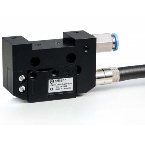
Converts the movement of key machine parts into electrical signals.
Designed for harsh industrial environments and resistant to various physical and environmental factors.
Magnetic band length can reach up to 50 meters.
Allows for either user-defined reference marks or external zero signal actuator.
LED on the reading head confirms reference mark detection.
Compressed air can be used to clean the rail surface, improving accuracy.
Two output signal options:
PCMT-F: Square-wave with built-in interpolation electronics.
PCMT-AV: Sinusoidal signal requiring external interpolation.
Features
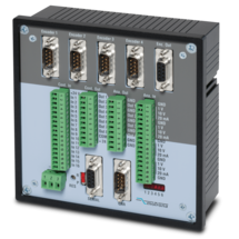
MC700 is a universal motion controller for 1 to 4 axes, which can be assigned any motion control functions by loading firmware. Together with the firmware BY701 (see firmware), this controller offers excellent synchronous functions for 1 - 4 axes.The firmware offers all conceivable possibilities for the synchronization of drives, including the influence of phase position and the relative position between the drives and numerous index and print mark functions.
Optionally, a "physical master" or the built-in "virtual master axis" with programmable speeds and ramps can be used as the master drive.
The number of successive axes can be extended arbitrarily via a cascading output.
MC700 controllers can be operated via an external control terminal, serial interface or optional via CANBUS (MC700/CI). PC operator software is included.
PROFIBUS connection possible via gateway PB251 (see accessories)
Features
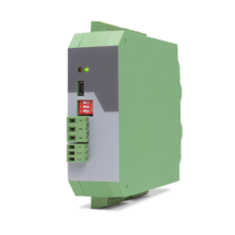
6-wire connection for one strain gauge full bridge sensor
4 control inputs [HTL/PNP]
1 analog output ±10 V, 0/4 ... 20 mA, 16 bit
4 control outputs for signalling different operation states
Power supply 18 ... 30 VDC
Functions for scaling and linking the sensor signals (e.g. A+B, A-B, ...)
Adjustable bridge voltage per sensor from 3 VDC ... 10 VDC
Sensitivity of the sensor inputs 1 ... 10 mV
Transmission of the sensor data via RS485
Programming via USB and the user interface OS (freeware)
Protection class IP20
Compact housing for mounting on 35 mm top-hat rail (according to EN 60715)
Features
6-wire connection for two independent strain gauge full bridge sensors
4 control inputs [HTL/PNP]
2 independent analog outputs ±10 V, 0/4 ... 20 mA, 16 bit
4 control outputs for signalling different operation states
Power supply 18 ... 30 VDC
Functions for scaling and linking the sensor signals (e.g. A+B, A-B, ...)
Adjustable bridge voltage per sensor from 3 VDC ... 10 VDC
Sensitivity of the sensor inputs 1 ... 10 mV
Transmission of the sensor data via RS485
Programming via USB and the user interface OS (freeware)
Protection class IP20
Compact housing for mounting on 35 mm top-hat rail (according to EN 60715)
Features
Pulse input with format A, B, 90° [HTL] or A, /A, B, /B [RS422], also possible for single-channel
Input frequency up to 500 kHz
2 output relays with potential-free change-over contact (forward, reward and zero motion)
2 transistor outputs with High-Side-Driver, short-circuit-proof
Power supply 17 ... 30 VDC
Snap-on housing for top hat rail (according to EN 60715)
DIL switch for setup of input characteristic and definition of standstill
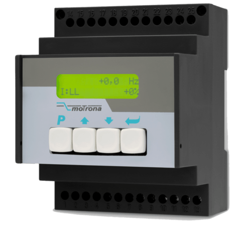
Features
Pulse input with format A, B, 90° [HTL] or A, /A, B, /B [RS422], also possible for single-channel
Input frequency up to 1 MHz
3 output relays
14 Bit analog output for ±10 V or 0/4 ... 20 mA
Power supply 17 ... 30 VDC
Auxiliary voltage output +5 V for the supply of TTL encoders
Snap-on housing for top hat rail (according to EN 60715)
LCD display, backlighted
Setup via keys or via PC by serial RS232 interface
Features
Pulse input with format A, B, 90° [HTL] or A, /A, B, /B [RS422], also possible for single-channel
Input frequency up to 1 MHz
3 fast transistor switching outputs [PNP]
14 bit analog output for ±10 V or 0/4 ... 20 mA
Power supply 17 ... 30 VDC
Auxiliary voltage output +5 V for the supply of TTL encoders
Snap-on housing for top hat rail (according to EN 60715)
LCD display, backlighted
Setup via keys or via PC by serial RS232 interface
Features
Pulse input with format A, B, 90° [HTL] or A, /A, B, /B [RS422], also possible for single-channel
Input frequency up to 1 MHz
3 output relays
Power supply 17 ... 30 VDC
Auxiliary voltage output +5 V for the supply of TTL encoders
Snap-on housing for top hat rail (according to EN 60715)
LCD display, backlighted
Setup via keys or via PC by serial RS232 interface
Features
Input frequency up to 500 kHz with HTL or 1 MHz with RS422 / TTL
4 pulse outputs, formats correspond to those of the input signals, but with individual assignment of the output level for each output
BUS interface for quick and easy connection of the modules
Power supply 10 ... 30 VDC
Signal delay time 160 ns
Input level at RS422 / TTL (differential voltage > 0.5 V),
Input level at HTL differential (differential voltage > 2 V),
Input level at HTL asymmetric low: 0 ... 6 V, high: 8 ... 40 V
Input level at TTL (asymmetrical): LOW < 0.8 V, HIGH >2.0 V
Compact housing for mounting on 35 mm top hat rail (according to EN 60715)
Dimensions W x H x D = 34 x 118 x 140 mm (1,34 x 4,65 x 5,51")
Page load link