Skip to content
Features
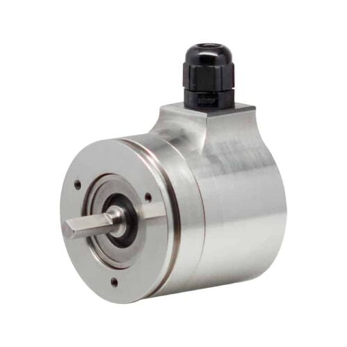
Industry-standard Size 20 (50.8mm diameter) stainless steel package
Flange and servo mounting
Up to 30,000 PPR
80 lb maximum axial and radial shaft loading
IP67 sealing available
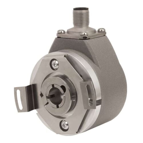
Features
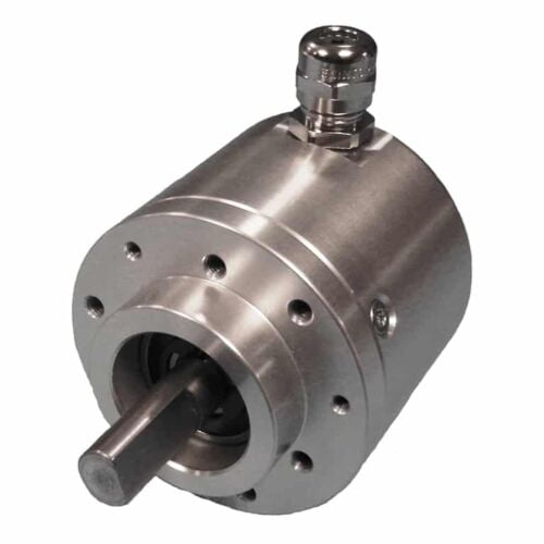
Industry-standard Size 58 (58mm diameter) stainless steel package
Up to 30,000 PPR
36 Kg max. Axial and radial shaft loading
100° C operating temperature available
IP65 sealing available
Manufactured in Food Grade Stainless Steel
Features
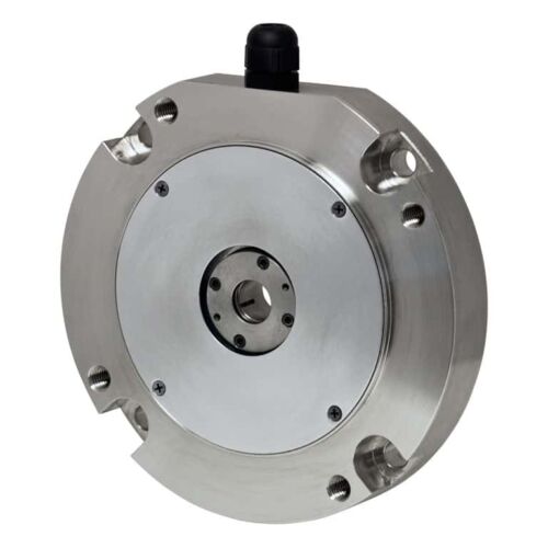
C-Face thru-bore encoder with stainless steel housing
Fits NEMA Size 56C thru 184C motor faces (4.5" AK)
Slim profile—only 25.4mm deep
Incorporates Opto-ASIC technology
Resolutions to 4096 PPR
Features
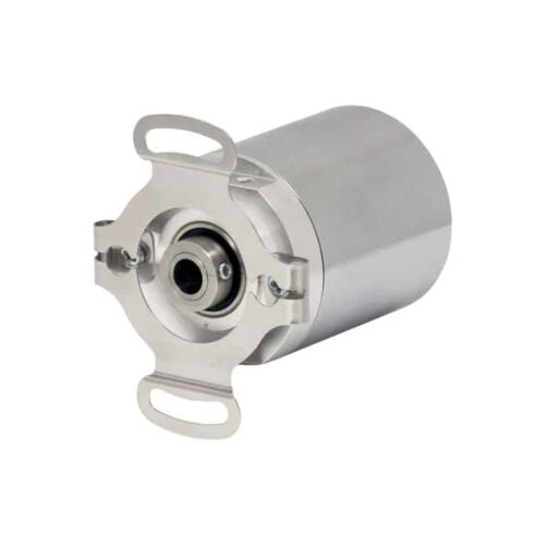
Low profile—40mm
Thru-bore or hollow-bore styles
Industrial-grade, heavy-duty housing
State-of-the-art Opto-ASIC circuitry
Features
Standard Size 36mm package
Durable magnetic technology
Up to 14 bits of single-turn resolution
SSI and CANopen communications
Proven turns counting technology—no gears or batteries
Flex mount eliminates couplings and is ideal for motors or shafts
Features
Up to 14 Bits of Single-Turn Resolution
SSI and CANopen Communications
58 mm Diameter
Durable Magnetic Technology
Retains Absolute Position After a Power Outage
Features
2 pulse inputs with format A, B, 90° [HTL] or A, /A, B, /B [RS422]
4 control inputs for HTL / PNP / NPN / Namur signals [10 ... 30 VDC]
Input frequency up to 300 kHz
4 fast transistor outputs, push-pull, short-circuit-proof [5 … 30 VDC]
1 scalable 14-bit analog output (±10 V or 0/4 … 20 mA)
Loop time approx. 250 µs
Power supply 24 VAC and 17 … 40 VDC
Compact norm panel housing (according to EN 60715)
Top hat rail mounting by using SM300 support brackets (option)
Setup via keys or via PC by serial RS232 interface
PROFIBUS connection via Motrona gateway PB251
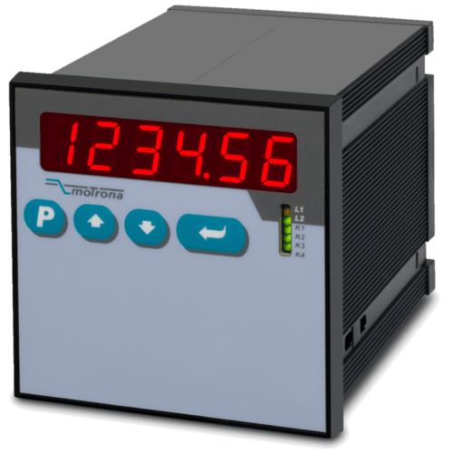
Features
2 pulse inputs with format A, B, 90° [HTL] or A, /A, B, /B [RS422]
4 control inputs for HTL / PNP / NPN / Namur signals [10 ... 30 VDC]
Input frequency up to 300 kHz
4 fast transistor outputs, push-pull, short-circuit-proof [5 … 30 VDC]
4 potential-free changeover relay outputs
1 scalable 14-bit analog output (±10 V or 0/4 … 20 mA)
Loop time approx. 250 µs
Power supply 24 VAC and 17 … 40 VDC
Compact norm panel housing (according to EN 60715)
Top hat rail mounting by using SM600 support brackets (option)
Setup via keys or via PC by serial RS232 interface
PROFIBUS connection via Motrona gateway PB251
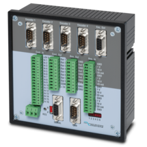
Features
MC700 is a universal motion controller for 1 to 4 axes, which can be assigned any motion control functions by loading firmware. Together with the firmware BY701 (see firmware), this controller offers excellent synchronous functions for 1 - 4 axes.The firmware offers all conceivable possibilities for the synchronization of drives, including the influence of phase position and the relative position between the drives and numerous index and print mark functions.
Optionally, a "physical master" or the built-in "virtual master axis" with programmable speeds and ramps can be used as the master drive.
The number of successive axes can be extended arbitrarily via a cascading output.
MC700 controllers can be operated via an external control terminal, serial interface or optional via CANBUS (MC700/CI). PC operator software is included.
PROFIBUS connection possible via gateway PB251 (see accessories)
Features
6-wire connection for one strain gauge full bridge sensor
4 control inputs [HTL/PNP]
1 analog output ±10 V, 0/4 ... 20 mA, 16 bit
4 control outputs for signalling different operation states
Power supply 18 ... 30 VDC
Functions for scaling and linking the sensor signals (e.g. A+B, A-B, ...)
Adjustable bridge voltage per sensor from 3 VDC ... 10 VDC
Sensitivity of the sensor inputs 1 ... 10 mV
Transmission of the sensor data via RS485
Programming via USB and the user interface OS (freeware)
Protection class IP20
Compact housing for mounting on 35 mm top-hat rail (according to EN 60715)
Features
6-wire connection for two independent strain gauge full bridge sensors
4 control inputs [HTL/PNP]
2 independent analog outputs ±10 V, 0/4 ... 20 mA, 16 bit
4 control outputs for signalling different operation states
Power supply 18 ... 30 VDC
Functions for scaling and linking the sensor signals (e.g. A+B, A-B, ...)
Adjustable bridge voltage per sensor from 3 VDC ... 10 VDC
Sensitivity of the sensor inputs 1 ... 10 mV
Transmission of the sensor data via RS485
Programming via USB and the user interface OS (freeware)
Protection class IP20
Compact housing for mounting on 35 mm top-hat rail (according to EN 60715)
Features
Strain gauge input, 6-wire connection
Input pt100 and thermocouples (J and K)
3 control inputs for HTL / PNP signals
Power supply 18 ... 30 VDC
Adjustable bridge voltage 3 VDC to 10 VDC
1 … 10 mV sensitivity
Standard installation housing with 96 x 48 mm and protection class IP65
Bright and high-contrast graphic display with event-dependent color variants
Emulation of a 7-segment display with symbols and units
Intuitive and simple parameterization through plain text and touchscreen
Numerous functions such as tare, filter, averaging
Linearization with 24 support points
Options
Option AC: Power supply 115 ... 230 VAC
Option AO: 16-bit analog output, 4 control outputs, serial RS232 interface
Option AR: 16-bit analog output, 4 control outputs, serial RS485 interface
Option CO: 4 control outputs, serial RS232 interface
Option CR: 4 control outputs, serial RS485 interface
Option RL: 2 relay outputs
Option IO: IO-Link Device V1.1
Options can be combined.
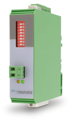
Features
Control input with format [HTL]
2 SSI inputs with format [RS422]
Cutt-off frequency 100 kHz ... 1 MHz
2 encoder inputs, short-circuit-proof
1 SSI output with format [RS422]
Power supply 12 ... 30 V DC
Current consumption (unloaded) 50 mA
Encoder supply 2 x 125mA (Vin – 2 V) short-circuit-proof
Delay / Output / Input100 ns
Operation temperature : 0 ... 45 °C (32 ... 113 °F)
SSI pause time min. 25 ns
Switching time is synchronized automatically with the next SSI break
Cascadable for more SSI encoders
All connections via pluggable screw terminal block
Snap-on housing for top-hat rail (according to EN 60715)
LEDs for indication of the input pulses
Dimension W x H x D = 22,5 x 121 x 112 mm (8.86 x 47.64 x 44.09'')
Plastic housing incl. plug
Features
1 Strain gauge input
3 VDC and 10 VDC bridge voltage per sensor connection
1 … 10 mV sensitivity
optionally 3 control inputs for PNP signals [10 ... 30 VDC]
IO link interface
Power supply 12 ... 30 VDC
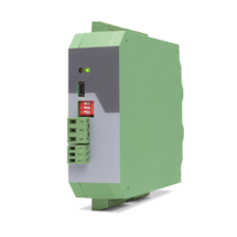
Compact housing for mounting on 35 mm DIN rail (according to EN 60715)
Features
1 SSI input (10 … 32 bit)
for single-turn and multiturn encoders
optionally 3 control inputs for PNP signals [10 ... 30 VDC]
IO link interface
Power supply 12 ... 30 VDC
Compact housing for mounting on 35 mm DIN rail (according to EN 60715)
Features
SSI input with format DATA+, DATA-, CLOCK+, CLOCK- up to 32 Bit
Impulse inputs A, B [HTL], A, /A, B, /B [RS422, HTL]
3 control inputs (Hold) for PNP signals [10 ... 30 VDC]
Start-stop interface for absolute transducers and magnetostrictive sensors
Input frequency up to 1 MHz
25-bit parallel output push-pull in BCD, binary or Gray code format
Power supply 18 ... 30 VDC
Compact housing for mounting on 35 mm top-hat rail (according to EN 60715)
Features
SSI input DATA+, DATA-, CLOCK+, CLOCK- [RS422], 32 Bit
SSI clock frequency up to 1 MHz
Analog output ±10 V or 0/4 ... 20 mA, 16 Bit
Power supply 18 ... 30 VDC
Snap-on housing for top-hat rail (according to EN 60715)
Setup via operator software OS6.0
Serial RS232- / RS485 interface
Pulse inputs A, B [HTL], A, /A, B, /B [RS422, HTL]
Start-stop interface for absolute transducers and magnetostrictive sensors
USB interface and RS232/RS485 interface for configuration and serial readout
Features
4 pulse inputs with format A, /A, B, /B [RS422]
4 scalable 12-bit analog inputs for ±10 V or 0/4 ... 20 mA
8 control inputs for PNP signals [10 ... 30 VDC]
4 scalable 12-bit analog outputs for ±10 V or 0/4 ... 20 mA
Short loop time (depending on application)
Power supply 18 ... 35 VDC
Snap-on housing for top-hat rail (according to EN 60715)
Setup via Windows operator software (free of charge)
OnBoard interfaces: RS232 and CANopen
Features
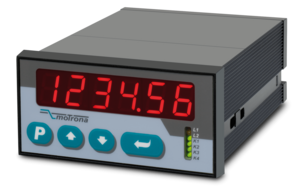
High level of external safety (Recognition of electrical or mechanical errors in the machinery/sensor systems/wirings etc.)
High level of internal safety (detection of internal errors and failures of the device components)
2 Pulse inputs with format A, B, 90° [HTL] or A, /A, B, /B [RS422]
4 control inputs for PNP / NPN / Namur signals [10 ... 30 VDC]
6 logical inputs for PNP signals [10 ... 30 VDC]
Input frequency up to 500 kHz
4 fast transistor outputs with push-pull characteristics, short-circuit-proof [5 ... 30 VDC]
4 forced-guided redundant output relays with potential free change-over contact
Serial interface RS232 and RS485
Power supply 24 VAC and 17 ... 40 VDC
Compact norm panel housing
6 digits LED display with 15 mm height
Display range -199999 ... 999999
Setup by keys or PC via serial RS232 Interface
Dimension B x H x T = 110 x 48 x 140 mm (4,33 x 1,89 x 5,51")
Features
20-bit parallel input with format BCD, binary or Gray-Code
Input frequency: fast encoder 5 kHz, auto-transmit / data logging 0.5 kHz
4 status outputs, with push-pull characteristics, short-circuit-proof [5 ... 30 VDC]
Power supply 10 ... 30 VDC
Snap-on housing for top-hat rail (according to EN 60715)
Serial RS232 / RS485 interface
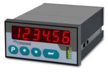
Features
2 pulse inputs with format A, B, 90° [HTL] or A, /A, B, /B [RS422]
4 control inputs for HTL / PNP / NPN / Namur signals [10 ... 30 VDC]
Input frequency up to 300 kHz
4 fast transistor outputs, push-pull, short-circuit-proof [5 … 30 VDC]
1 scalable 14-bit analog output (±10 V or 0/4 … 20 mA)
Loop time approx. 250 µs
Defining incremental dimensions via keyboard
Power supply 24 VAC and 17 … 40 VDC
Compact norm panel housing (according to EN 60715)
Top hat rail mounting by using SM300 support brackets (option)
Setup via keys or via PC by serial RS232 interface
PROFIBUS connection via mMotrona gateway PB251
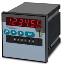
Features
2 pulse inputs with format A, B, 90° [HTL] or A, /A, B, /B [RS422]
4 control inputs for HTL / PNP / NPN / Namur signals [10 ... 30 VDC]
Input frequency up to 300 kHz
4 fast transistor outputs, push-pull, short-circuit-proof [5 … 30 VDC]
1 scalable 14-bit analog output (±10 V or 0/4 … 20 mA)
Loop time approx. 250 µs
Defining incremental dimensions via keyboard or BCD decade switch on the front
Power supply 24 VAC and 17 … 40 VDC
Compact norm panel housing (according to EN 60715)
Top hat rail mounting by using SM600 support brackets (option)
Setup via keys or via PC by serial RS232 interface
PROFIBUS connection via Motrona gateway PB251
Dimension 96 x 96 x 140 mm (3,78 x 3,78 x 5,51")
Features
Pulse inputs A, B [HTL], A, / A, B, / B [RS422, HTL]
SSI input in the format DATA +, DATA-, CLOCK +, CLOCK- up to 32 bits
Start-stop interface for absolute transducers and magnetostrictive sensors
3 control inputs (hold) for PNP signals [10 ... 30 VDC]
Input frequency up to 1 MHz
25-bit parallel output push-pull in BCD, binary or Gray code format
Power supply 18 ... 30 VDC
Compact housing for mounting on 35 mm top-hat rail (according to EN 60715)
Features
Pulse inputs A, B [HTL], A, /A, B, /B [RS422, HTL]
Input frequency up to 1 MHz [RS422], 200 kHz [HTL]
Analog output ±10 V or 0/4 ... 20 mA, 16 Bit
Power supply 18 ... 30 VDC
Snap-on housing for top-hat rail (according to EN 60715)
Setup via operator software OS6.0
Serial RS232- / RS485 interface
SSI input DATA+, DATA-, CLOCK+, CLOCK- [RS422], 32 Bit
Start-stop interface for absolute transducers and magnetostrictive sensors
USB interface and RS232/RS485 interface for configuration and serial readout
Page load link