Skip to content
Features
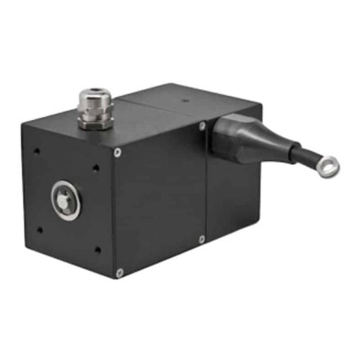
Low-cost linear solution
Imperial and Metric Options
IP65 sealing available
Up to 1.27M or 50” Full Stroke Length
Features
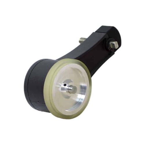
Encoder and measuring wheel solution integrated into one compact unit
Spring-loaded torsion arm makes wheel pressure adjustments a snap
Easily installed in a vertical, horizontal or upside-down orientation
Operates over a variety of surfaces at speeds up to 3000 feet per minute
The integrated module simplifies your system design, reducing cost
Features
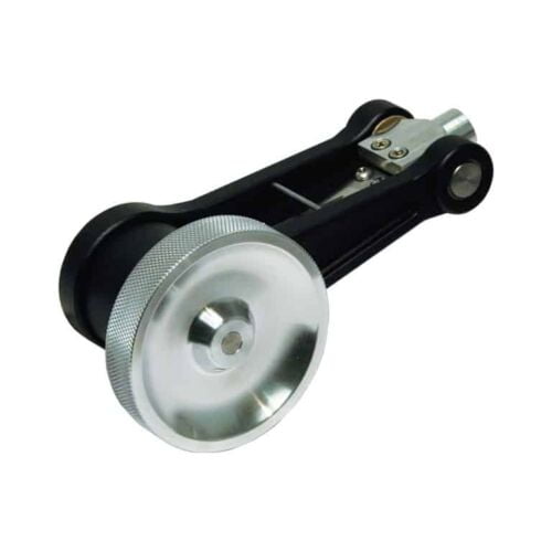
Integrated heavy-duty encoder and measuring wheel in one
Spring-loaded torsion arm for quick wheel pressure adjustments
Easily installed in a vertical, horizontal or upside-down orientation
Operates over a variety of surfaces at speeds up to 3000 feet per minute
Integrated module simplifies system design, reducing cost
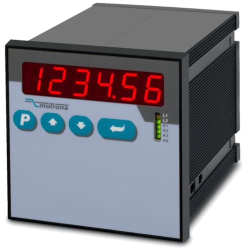
Features
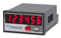
Scalable 14-bit analog input for 0 ... 10 V or 0/4 ... 20 mA
Power supply 24 VDC
Miniature norm panel housing
5 digits LED display with 8 mm height
Display range -19999 ... 99999, adjustable zero and full-scale value
Latch input to freeze the display, minimum/maximum record memory
Easy to set up with only two front keys and menu support
Delivery includes adapter frame for 50 x 25 mm cut out and label set with dimensions
Front dimension 48 x 24 x 59 mm (1.89 x 0.945 x 2.322")
Features
2 universal 16-bit analog inputs for ±10 V or 0/4 … 20 mA
3 control inputs for HTL / PNP signals
Power supply 18 ... 30 VDC
24 V auxiliary output for encoder supply
High accuracy reference output 10 V for potentiometers > 1 kOhm
3.78 x 1.89-inch norm panel housing and IP65 protection
Bright and high-contrast display with event-dependent color variations
Emulation of a 7-segment display inclusively icons and units
Intuitive and easy parameterization by plain text and touchscreen
Operating modes for visualization of INPUT 1, INPUT 2 or combinations of IN1 + IN2, IN1 - IN2, IN1 x IN2, IN1: IN2
Numerous features, e. g. Ttara, filters, averaging
Linearization with 24 control points
Option IO (= IO-Link Device)
Data transfer via COM3 (230,4 kBaud)
Cycle times < 3 msec
Process data IN 32 Byte (6 x process values from AX350):
- Analog value 1 (scaled / linearized) and unit
- Analog value 2 (scaled / linearized) and unit
- Analog value 1 (scaled / linearized) with totalisation and unit
- Analog value 2 (scaled / linearized) with totalisation and unit
- Shortcut analogue value 1 (scaled / linearized) with analogue value 2 (scaled / linearized) and unit
- Shortcut totalisator analogue value 1 (scaled / linearized) with totalisator analogue value 2 (scaled / linearized) and unit
Process data Out 8 Byte (2 x IO-Link process values to AX350):
- IOL process value Out 1 with scaling, adjustable decimal point and programmable units
- IOL process values Out 2 with scaling, adjustable decimal point and programmable units
Combinable with further options:
Option AC: Power supply 115 ... 230 VAC
Option AO: 16-bit analog output, 4 control outputs, serial RS232 interface
Option AR: 16-bit analog output, 4 control outputs, serial RS485 interface
Option CO: 4 control outputs, serial RS232 interface
Option CR: 4 control outputs, serial RS485 interface
Option RL: 2 relay outputs
Features
USB to RS232 converter (compatible with all existing Windows versions)
Serial RS232 cable (for connection between the converter and motrona unit)
One connector Sub-D-9 (male)
One connector Sub-D-9 (female)
Length 3 m (approx. 10 feet)
Windows driver CD enclosed
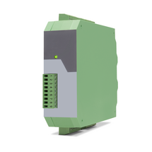
Features
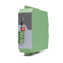
6-wire connection for one strain gauge full bridge sensor
4 control inputs [HTL/PNP]
1 analog output ±10 V, 0/4 ... 20 mA, 16 bit
4 control outputs for signalling different operation states
Power supply 18 ... 30 VDC
Functions for scaling and linking the sensor signals (e.g. A+B, A-B, ...)
Adjustable bridge voltage per sensor from 3 VDC ... 10 VDC
Sensitivity of the sensor inputs 1 ... 10 mV
Transmission of the sensor data via RS485
Programming via USB and the user interface OS (freeware)
Protection class IP20
Compact housing for mounting on 35 mm top-hat rail (according to EN 60715)
Features
6-wire connection for two independent strain gauge full bridge sensors
4 control inputs [HTL/PNP]
2 independent analog outputs ±10 V, 0/4 ... 20 mA, 16 bit
4 control outputs for signalling different operation states
Power supply 18 ... 30 VDC
Functions for scaling and linking the sensor signals (e.g. A+B, A-B, ...)
Adjustable bridge voltage per sensor from 3 VDC ... 10 VDC
Sensitivity of the sensor inputs 1 ... 10 mV
Transmission of the sensor data via RS485
Programming via USB and the user interface OS (freeware)
Protection class IP20
Compact housing for mounting on 35 mm top-hat rail (according to EN 60715)
Features
Strain gauge input, 6-wire connection
Input pt100 and thermocouples (J and K)
3 control inputs for HTL / PNP signals
Power supply 18 ... 30 VDC
Adjustable bridge voltage 3 VDC to 10 VDC
1 … 10 mV sensitivity
Standard installation housing with 96 x 48 mm and protection class IP65
Bright and high-contrast graphic display with event-dependent color variants
Emulation of a 7-segment display with symbols and units
Intuitive and simple parameterization through plain text and touchscreen
Numerous functions such as tare, filter, averaging
Linearization with 24 support points
Options
Option AC: Power supply 115 ... 230 VAC
Option AO: 16-bit analog output, 4 control outputs, serial RS232 interface
Option AR: 16-bit analog output, 4 control outputs, serial RS485 interface
Option CO: 4 control outputs, serial RS232 interface
Option CR: 4 control outputs, serial RS485 interface
Option RL: 2 relay outputs
Option IO: IO-Link Device V1.1
Options can be combined.
Features
Pulse input with format A, B, 90° [HTL] or A, /A, B, /B [RS422], also possible for single-channel
Input frequency up to 500 kHz
2 output relays with potential-free change-over contact (forward, reward and zero motion)
2 transistor outputs with High-Side-Driver, short-circuit-proof
Power supply 17 ... 30 VDC
Snap-on housing for top hat rail (according to EN 60715)
DIL switch for setup of input characteristic and definition of standstill
Features
Pulse input with format A, B, 90° [HTL] or A, /A, B, /B [RS422], also possible for single-channel
Input frequency up to 1 MHz
3 output relays
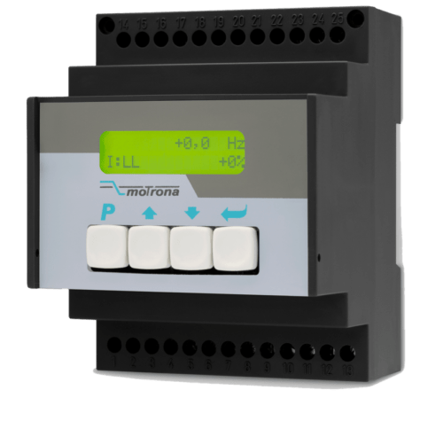
14 Bit analog output for ±10 V or 0/4 ... 20 mA
Power supply 17 ... 30 VDC
Auxiliary voltage output +5 V for the supply of TTL encoders
Snap-on housing for top hat rail (according to EN 60715)
LCD display, backlighted
Setup via keys or via PC by serial RS232 interface
Features
Pulse input with format A, B, 90° [HTL] or A, /A, B, /B [RS422], also possible for single-channel
Input frequency up to 1 MHz
3 fast transistor switching outputs [PNP]
14 bit analog output for ±10 V or 0/4 ... 20 mA
Power supply 17 ... 30 VDC
Auxiliary voltage output +5 V for the supply of TTL encoders
Snap-on housing for top hat rail (according to EN 60715)
LCD display, backlighted
Setup via keys or via PC by serial RS232 interface
Features
Pulse input with format A, B, 90° [HTL] or A, /A, B, /B [RS422], also possible for single-channel
Input frequency up to 1 MHz
3 output relays
Power supply 17 ... 30 VDC
Auxiliary voltage output +5 V for the supply of TTL encoders
Snap-on housing for top hat rail (according to EN 60715)
LCD display, backlighted
Setup via keys or via PC by serial RS232 interface
Features
Sub-D-9 connectors (male) on both sides
cable length 10 cm (approx. 3.4")
Features
1 Strain gauge input
3 VDC and 10 VDC bridge voltage per sensor connection
1 … 10 mV sensitivity
optionally 3 control inputs for PNP signals [10 ... 30 VDC]
IO link interface
Power supply 12 ... 30 VDC
Compact housing for mounting on 35 mm DIN rail (according to EN 60715)
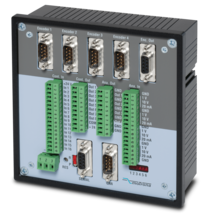
Features
4 pulse inputs with format A, /A, B, /B [RS422]
4 scalable 12-bit analog inputs for ±10 V or 0/4 ... 20 mA
8 control inputs for PNP signals [10 ... 30 VDC]
4 scalable 12-bit analog outputs for ±10 V or 0/4 ... 20 mA
Short loop time (depending on application)
Power supply 18 ... 35 VDC
Snap-on housing for top-hat rail (according to EN 60715)
Setup via Windows operator software (free of charge)
OnBoard interfaces: RS232 and CANopen
Features
High level of external safety (Recognition of electrical or mechanical errors in the machinery/sensor systems/wirings etc.)
High level of internal safety (detection of internal errors and failures of the device components)
2 Pulse inputs with format A, B, 90° [HTL] or A, /A, B, /B [RS422]
4 control inputs for PNP / NPN / Namur signals [10 ... 30 VDC]
6 logical inputs for PNP signals [10 ... 30 VDC]
Input frequency up to 500 kHz
4 fast transistor outputs with push-pull characteristics, short-circuit-proof [5 ... 30 VDC]
4 forced-guided redundant output relays with potential free change-over contact
Serial interface RS232 and RS485
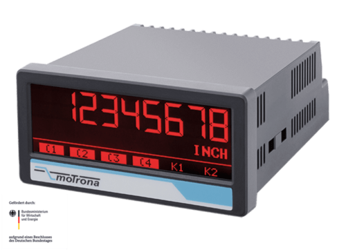
Power supply 24 VAC and 17 ... 40 VDC
Compact norm panel housing
6 digits LED display with 15 mm height
Display range -199999 ... 999999
Setup by keys or PC via serial RS232 Interface
Dimension B x H x T = 110 x 48 x 140 mm (4,33 x 1,89 x 5,51")
Features
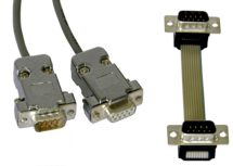
1 connector Sub-D-9 (male)
1 connector Sub-D-9 (female)
cable length 3 m (approx. 10 feet)
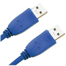
Features
USB cable for connection between PC and the Motrona unit UZ210
Both connectors are type A
Cable length 2 m (approx. 6.5 feet)
Features
Pulse inputs A, B [HTL], A, / A, B, / B [RS422, HTL]
SSI input in the format DATA +, DATA-, CLOCK +, CLOCK- up to 32 bits
Start-stop interface for absolute transducers and magnetostrictive sensors
3 control inputs (hold) for PNP signals [10 ... 30 VDC]
Input frequency up to 1 MHz
25-bit parallel output push-pull in BCD, binary or Gray code format
Power supply 18 ... 30 VDC
Compact housing for mounting on 35 mm top-hat rail (according to EN 60715)
Features
Pulse inputs A, B [HTL], A, /A, B, /B [RS422, HTL]
Input frequency up to 1 MHz [RS422], 200 kHz [HTL]
Analog output ±10 V or 0/4 ... 20 mA, 16 Bit
Power supply 18 ... 30 VDC
Snap-on housing for top-hat rail (according to EN 60715)
Setup via operator software OS6.0
Serial RS232- / RS485 interface
SSI input DATA+, DATA-, CLOCK+, CLOCK- [RS422], 32 Bit
Start-stop interface for absolute transducers and magnetostrictive sensors
USB interface and RS232/RS485 interface for configuration and serial readout
Page load link