Skip to content
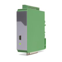
Features
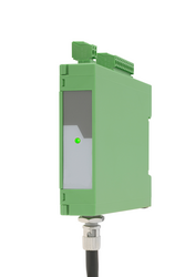
4 independent input channels with format A, B, C, D [HTL] or A, /A, B, /B, C, /C, D, /D [RS422], also possible for single-channel
4 output channels with format A, B, C, D [HTL] or A, /A, B, /B, C, /C, D, /D [RS422]
Maximum input frequency 1 MHz
Very short conversion time < 300 ns
Optical wavelength 1300 nm
Transmission distance up to 3000 meters
Power supply 5 VDC (for LW213)
Power supply 10 ... 30 VDC (for LW213-1, LW213-2, LW213-3)
Snap-on housing for top-hat rail (according to EN 60715)
Pre-configured optical fibres are available
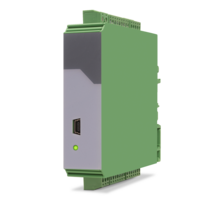
Features
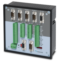
4 pulse inputs with format A, /A, B, /B [RS422]
4 scalable 12-bit analog inputs for ±10 V or 0/4 ... 20 mA
8 control inputs for PNP signals [10 ... 30 VDC]
4 scalable 12-bit analog outputs for ±10 V or 0/4 ... 20 mA
Short loop time (depending on application)
Power supply 18 ... 35 VDC
Snap-on housing for top-hat rail (according to EN 60715)
Setup via Windows operator software (free of charge)
OnBoard interfaces: RS232 and CANopen
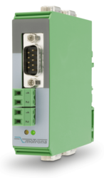
Features
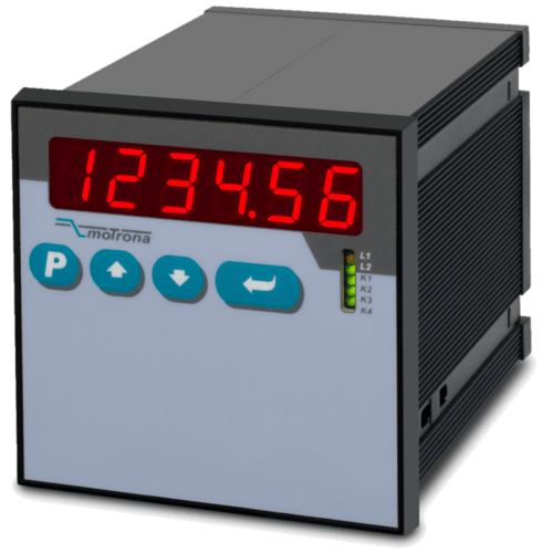
The MC800 hardware is a universal motion controller, which serves for sophisticated control tasks in today’s machine engineering and drive technology. This motion controller can cover a wide application range due to the function features and settings of the equipped control firmware.
Typical control applications are e.g. drive synchronization of a master and slave axis, index and print mark evaluation, rotating cross cutters, flying and eccentric shears, label printing machines and many more.
The unique feature of the MC800 is the integrated tandem drive controller. This enables to reach the acceleration requirements of heavy loads by splitting the necessary power to two independent drives.
Further features are the flexible and combinable input configuration for different types of encoders, measuring systems and sensors, the high frequency range up to 2 MHz and the adaptive interface architecture.
Due to an extremely short position loop time of 250 µs, a self-optimizing polynomial motion profile, and excellent accuracy - even at high line speeds, the MC800 ensures a very smooth motion with maximum protection of the mechanical parts.
Features
High level of external safety (Recognition of electrical or mechanical errors in the machinery/sensor systems/wirings etc.)
High level of internal safety (detection of internal errors and failures of the device components)
2 Pulse inputs with format A, B, 90° [HTL] or A, /A, B, /B [RS422]
4 control inputs for PNP / NPN / Namur signals [10 ... 30 VDC]
6 logical inputs for PNP signals [10 ... 30 VDC]
Input frequency up to 500 kHz
4 fast transistor outputs with push-pull characteristics, short-circuit-proof [5 ... 30 VDC]
4 forced-guided redundant output relays with potential free change-over contact
Serial interface RS232 and RS485
Power supply 24 VAC and 17 ... 40 VDC
Compact norm panel housing
6 digits LED display with 15 mm height
Display range -199999 ... 999999
Setup by keys or PC via serial RS232 Interface
Dimension B x H x T = 110 x 48 x 140 mm (4,33 x 1,89 x 5,51")
Features
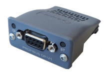
Internal power supply 3,3 V
Ambient temperature 0° C ... +60° C / 32° F ... 140° F (operating), -40° C ... +70° C / -40 ... 158° F (storage)
9600 Bit/s ... 12 MBit/s Baud rates
SUB-D-9-pin female, galvanically isolated
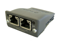
Features
Internal power supply 3,3 V
Ambient temperature 0° C ... +60° C (operating), -40° C ... +70° C (storage)
100 MBit/s Vollduplex
2 Ethernet-Ports RJ45 with integrated switch, galvanically isolated
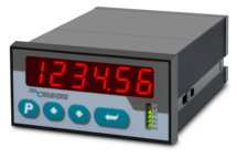
Features
2 pulse inputs with format A, B, 90° [HTL] or A, /A, B, /B [RS422]
4 control inputs for HTL / PNP / NPN / Namur signals [10 ... 30 VDC]
Input frequency up to 300 kHz
4 fast transistor outputs, push-pull, short-circuit-proof [5 … 30 VDC]
1 scalable 14-bit analog output (±10 V or 0/4 … 20 mA)
Loop time approx. 250 µs
Defining incremental dimensions via keyboard
Power supply 24 VAC and 17 … 40 VDC
Compact norm panel housing (according to EN 60715)
Top hat rail mounting by using SM300 support brackets (option)
Setup via keys or via PC by serial RS232 interface
PROFIBUS connection via mMotrona gateway PB251
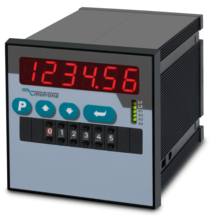
Features
2 pulse inputs with format A, B, 90° [HTL] or A, /A, B, /B [RS422]
4 control inputs for HTL / PNP / NPN / Namur signals [10 ... 30 VDC]
Input frequency up to 300 kHz
4 fast transistor outputs, push-pull, short-circuit-proof [5 … 30 VDC]
1 scalable 14-bit analog output (±10 V or 0/4 … 20 mA)
Loop time approx. 250 µs
Defining incremental dimensions via keyboard or BCD decade switch on the front
Power supply 24 VAC and 17 … 40 VDC
Compact norm panel housing (according to EN 60715)
Top hat rail mounting by using SM600 support brackets (option)
Setup via keys or via PC by serial RS232 interface
PROFIBUS connection via Motrona gateway PB251
Dimension 96 x 96 x 140 mm (3,78 x 3,78 x 5,51")
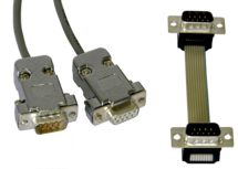
Features
1 connector Sub-D-9 (male)
1 connector Sub-D-9 (female)
cable length 3 m (approx. 10 feet)
Features
1 encoder input with format SIN+, SIN-, COS+, COS-, REF+, REF- [1 Vss]
Maximum sinus input frequency 500 kHz with max. 200 ns conversion time
4 signal outputs with format SIN+, SIN-, COS+, COS-, REF+, REF- [1 Vss]
Power supply 17 ... 30 VDC
Snap-on housing for top-hat rail (according to EN 60715)
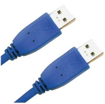
Features
USB cable for connection between PC and the Motrona unit UZ210
Both connectors are type A
Cable length 2 m (approx. 6.5 feet)
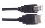
Features
USB cable for connection between PC operator software and Motrona DS device
USB connector type A on type B
Length 1,8 m
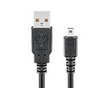
Features
USB cable for connection between PC and Motrona devices of the series IV/FU/PV/ZU210 and IP/FP/PP/ZP210
USB connector type A on type Mini B
Length 1,8 m
Features
Pulse inputs A, B [HTL], A, / A, B, / B [RS422, HTL]
SSI input in the format DATA +, DATA-, CLOCK +, CLOCK- up to 32 bits
Start-stop interface for absolute transducers and magnetostrictive sensors
3 control inputs (hold) for PNP signals [10 ... 30 VDC]
Input frequency up to 1 MHz
25-bit parallel output push-pull in BCD, binary or Gray code format
Power supply 18 ... 30 VDC
Compact housing for mounting on 35 mm top-hat rail (according to EN 60715)
Features
Pulse inputs A, B [HTL], A, /A, B, /B [RS422, HTL]
Input frequency up to 1 MHz [RS422], 200 kHz [HTL]
Analog output ±10 V or 0/4 ... 20 mA, 16 Bit
Power supply 18 ... 30 VDC
Snap-on housing for top-hat rail (according to EN 60715)
Setup via operator software OS6.0
Serial RS232- / RS485 interface
SSI input DATA+, DATA-, CLOCK+, CLOCK- [RS422], 32 Bit
Start-stop interface for absolute transducers and magnetostrictive sensors
USB interface and RS232/RS485 interface for configuration and serial readout
Features
Pulse input in format A, B, 90° [HTL]
Static Input for Set / Reset [HTL]
Input frequency up to 20 kHz
Power supply 24 VDC
Standardised miniature switch panel housing
with the dimensions 48 x 24 x 59 mm
6 decades LED display with 8 mm digit height
Display range -199999 ... 999999
Counting frequency 15 ... 60 kHz, depending on the operating mode
Programmable counting function (A with B as direction specification, sum A + B, difference A - B, position A / B with 90° phase offset)
Switchable pulse multiplication (x2, x4) as well as adjustable multiplier and divider 0.0001 ... 99.9999
Actual value memory (10 years)
Simple parameterisation via 2 front keys and menu navigation
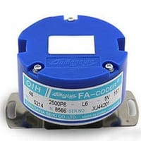
Features
Hollow Shaft Small Size
Resolution (Counts/Turn): 1,000∼12,000C/T
Output Phase: A, B, Z, EU, EV, EW Phase
Max Response Frequency: 200kHz
Supply Voltage: DC+5V
Consumption Current: 200mA Max
Output Form: Line Driver
Mounting Tolerance: Radial 0.05mm TIR Max, Axial 0.2mm Max, Shaft Runout 0.1°Max
Starting Torque: 9.8×10⁻³N⋅m (100gf⋅cm Max)
Protection: IP=40
Operating Temp. Range: -20∼+85°C
Vibration: 49m/s2(5G)
Shock: 980m/s2(100G)
Mass: 0.3kg Max
Page load link