Skip to content
Features
Type: Non-contact magnetic linear encoder (measures displacement without physical contact)
Measuring length: Up to 50 meters
Function: Converts linear movements of machine components into electrical signals with information about:
Value: Distance travelled
Direction: Forward or backward movement
Durability: Designed for harsh industrial environments and resistant to various contaminants and physical impacts.
Components:
Metal-based magnetic band (MP): Stores the encoded information
Reading head: Detects the magnetic field variations on the band and converts them into electrical signals
Profile rail (PS) with protective band: Provides mounting and protects the reading head
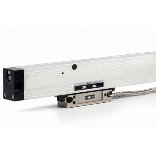
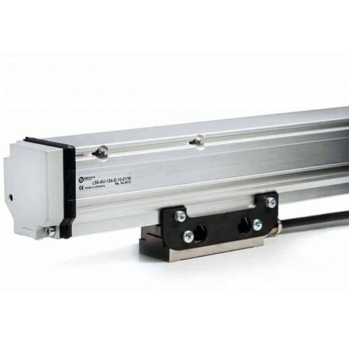
Features
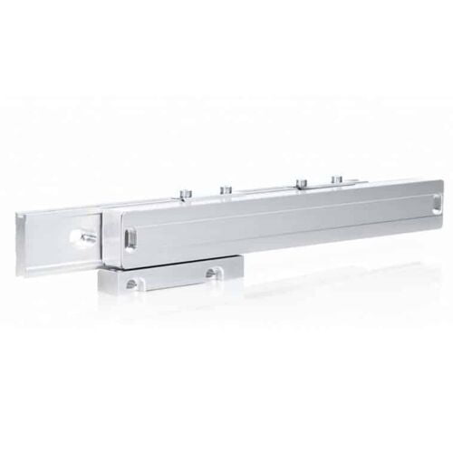
Type: Photoelectric linear displacement measuring device (measures changes in position)
Measuring length: Up to 2.040 mm
Grating period: Two options available: ±20 µm or ±40 µm (determines the smallest detectable movement)
Accuracy: Up to ±3 µm (indicates the encoder's closeness to the actual displacement)
Features
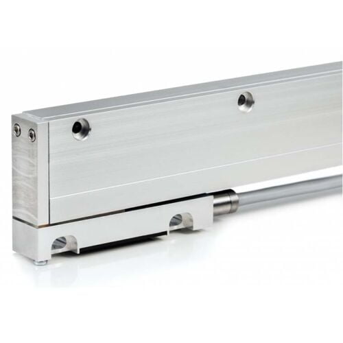
Measuring length: Up to 3.240 mm
Accuracy: Up to ±5 µm within any meter of its measuring length
Grating periods: Available in two options: ±20 µm and ±40 µm
Features
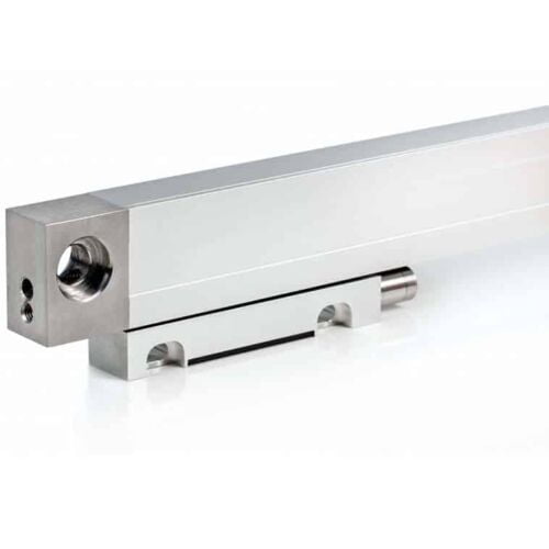
Similar to the L18 series: Shares most functionalities and specifications with the L18 series encoders.
Different housing fixation: Requires distinct mounting methods compared to the L18 series.
Improved thermal behaviour: More stable performance under different temperatures.
Features
Type: Photoelectric modular linear encoder
Measuring length:
Up to 20,000 mm (20 meters)
Can be even longer with special order
Accuracy: Up to ±3 µm
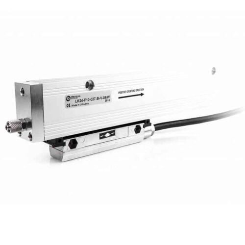
Features
Type: Incremental linear displacement measuring device (measures changes in position)
Measuring length: Up to 3.240 mm
Accuracy: Up to ±3 µm within any meter of its measuring length (accuracy scales with length)
Vibration resistance: More resistant to vibrations than the L18 series encoders
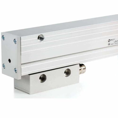
Features
Similar to the L35 series: Shares most functionalities and specifications with the L35 series encoders.
Different mounting parameters: Requires distinct mounting methods compared to the L35 series.
Measuring length: Up to 3.240 mm.
Enhanced vibration resistance: More resistant to vibrations than the L18 series encoders, making it suitable for applications with higher vibration levels.
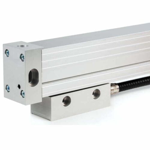
Features
Type: Incremental encoder
Thermal behaviour: Reproducible, indicating stability under temperature changes
Reading head: Reversible for flexibility in installation
Measuring length: Up to 3.240 mm
Accuracy: Up to ±3 µm within the measuring length
Features
Type: Incremental encoder
Measuring length: 3.240 mm to 30.040 mm
Grating period: 40 µm
Accuracy: Up to ±10 µm within the measuring length
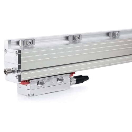
Features
Type: Photoelectric absolute linear encoder (measures absolute position)
Measuring length: Up to 3.240 mm (customizable)
Interface: SSI or BiSS serial interface for digital communication
Accuracy: Up to ±1 µm high accuracy
Optional incremental track: Provides 1Vpp incremental signal for applications requiring both absolute and incremental position data.
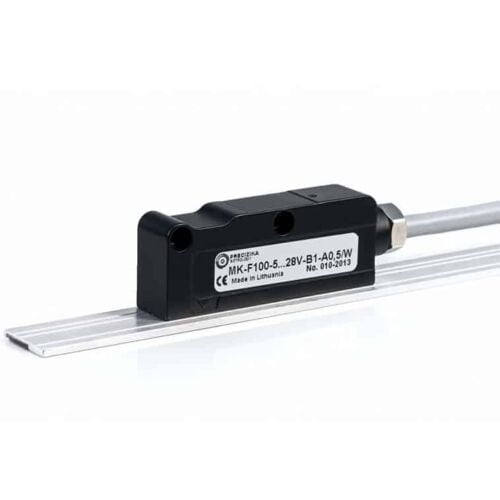
Features
Magnetic absolute linear encoder
MK has a measuring length of up to 50.000 mm
Accuracy can reach up to ±35 μm.
Encoder has two versions of serial interface - SSI or BiSS C
Optionally it can have 2 analog sinusoidal signals with phase shift 90°C and amplitude approx. 1Vpp.
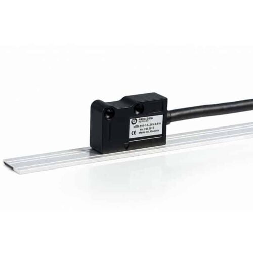
Features
Measuring length: Up to 50,000 mm (50 meters)
Accuracy: Up to ±25 micrometres (μm)
Customizable: Other parameters can be modified to meet specific needs
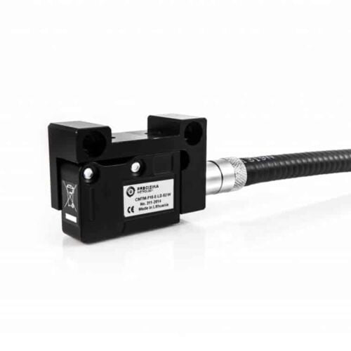
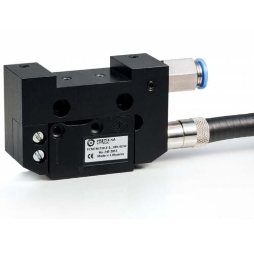
Features
Converts the movement of key machine parts into electrical signals.
Designed for harsh industrial environments and resistant to various physical and environmental factors.
Magnetic band length can reach up to 50 meters.
Allows for either user-defined reference marks or external zero signal actuator.
LED on the reading head confirms reference mark detection.
Compressed air can be used to clean the rail surface, improving accuracy.
Two output signal options:
PCMT-F: Square-wave with built-in interpolation electronics.
PCMT-AV: Sinusoidal signal requiring external interpolation.
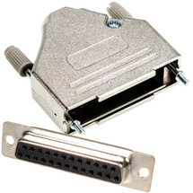
Features
Solder connection
Metallised plastic enclosure
Mounting screws included
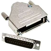
Features
Solder connection
Metallised plastic enclosure
Mounting screws included
Features
Solder connection
Metallised plastic enclosure
Mounting screws included
Features
Solder connection
Metallised plastic enclosure
Mounting screws included
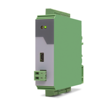
Features
Pulse input with format A, B, Z [HTL single-ended, TTL single-ended] or A, /A, B, /B, Z, /Z [RS422, HTL differential]
4 control inputs for HTL, PNP signals [10 ... 30 VDC]
Input and output frequency up to 1 MHz
3 incremental outputs with format A, /A, B, /B, Z, /Z, Push-Pull, [8 … 29 VDC]
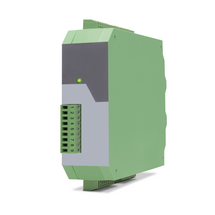
Power supply 9 ... 30 VDC
Snap-on housing for top-hat rail (acc. EN 60715)
Multiplier/divisor adjustable as quotient F1 / F2
Multiplication/division without cumulative residual errors
Additional functions such as jog, trim, offset and reference
Features
Pulse input with format A, B, 90° [HTL] or A, /A, B, /B, Z, /Z [RS422]
4 control inputs for PNP signals [10 ... 30 VDC]
Input and output frequency up to 1 MHz
Pulse output with format A, /A, B, /B, Z, /Z and
push-pull characteristic, [5 ... 30 VDC]
Power supply 11 ... 30 VDC
Snap-on housing for top-hat rail (according to EN 60715)
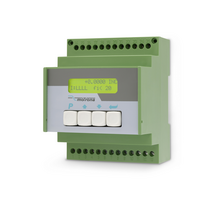
LCD backlighted
Setup via keys, RS232
The device multiplies an incoming frequency by a proportional factor F1 and a reciprocal factor F2. The two factors F1 and F2 are adjustable in the range of 0.0005 to 9.9999
All operation modes provide error-free frequency conversion, with full consideration of the A / B phase and direction of the quadrature signals, therefore no cumulative errors, even with continuous changes of directions and vibrations
Zero pulse generator: the frequency multiplier generates at the output an index signal with an adjustable pulse interval, which can be synchronized as needed with the zero pulse at the input
Features
Frequency inputs A, B [HTL], A, / A, B, / B [RS422, HTL]
3 control inputs (hold) for PNP signals [10 ... 30 VDC]
SSI input in the format DATA +, DATA-, CLOCK +, CLOCK- up to 32 bits
Start-stop interface for absolute transducers and magnetostrictive sensors
Input frequency up to 1 MHz
25-bit parallel output push-pull in BCD, binary or Gray code format
Power supply 18 ... 30 VDC
Compact housing for mounting on 35 mm top-hat rail (according to EN 60715)
Features
Pulse inputs A, B [HTL], A, /A, B, /B [RS422, HTL]
Input frequency up to 1 MHz [RS422], 200 kHz [HTL]
Analog output ±10 V or 0/4 ... 20 mA, 16 Bit
Power supply 18 ... 30 VDC
Snap-on housing for top-hat rail (according to EN 60715)
Setup via operator software OS6.0
Serial RS232- / RS485 interface
SSI input DATA+, DATA-, CLOCK+, CLOCK- [RS422], 32 Bit
Start-stop interface for absolute transducers and magnetostrictive sensors
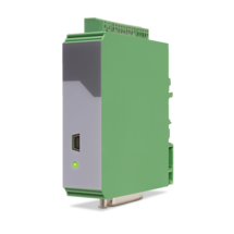
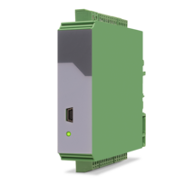
USB interface and RS232/RS485 interface for configuration and serial readout
Features
2 pulse inputs with format A, B, Z [HTL] or A, /A, B, /B, Z, /Z [RS422]
Input frequency up to 250 kHz for asymmetrical and up to 1 MHz for symmetric signals
2 control inputs for HTL / PNP signals [10 ... 30 VDC]
2 output channels with format A, B, Z [HTL] or A, /A, B, /B, Z, /Z [RS422], each output adjustable separately
Power supply 12 ... 30 VDC
Snap-on housing for top-hat rail (according to EN 60715)
Features
1 incremental input (A, /A, B, /B)
for HTL/TTL/RS422 for NPN/PNP/NAMUR encoders and sensors
optionally 3 control inputs for PNP signals [10 ... 30 VDC]
IO link interface
Power supply 12 ... 30 VDC
Compact housing for mounting on 35 mm DIN rail (according to EN 60715)
Features
Pulse input in format A, /A, B, /B, Z, /Z [RS422, HTL]
Pulse input in format A, B, Z [HTL]
Input frequency up to 1 MHz
Pulse output in format A, /A, B, /B, Z, /Z [RS422, HTL]
Pulse output in format A, B, Z [HTL]
Power supply 9 ... 30 VDC
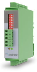
Settings via DIL switches
Level conversion (RS422, HTL single-ended, HTL differential, TTL and vice versa)
Division of two-track A / B pulses with adjustable ratio 1: 1 to 1: 4096
Division of the Z pulse with adjustable ratio 1: 1 to 1: 256
External HTL signals for various functions
Implementation between the two types of representations for the direction of rotation (A / B 90 °, A/B Dir and vice versa, Division possible)
Snap-on housing for top-hat rail (acc. EN 60715)
Dimension (B x H X T) 22,5 x 102 x 102 mm
Features
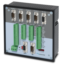
4 pulse inputs with format A, /A, B, /B [RS422]
4 scalable 12-bit analog inputs for ±10 V or 0/4 ... 20 mA
8 control inputs for PNP signals [10 ... 30 VDC]
4 scalable 12-bit analog outputs for ±10 V or 0/4 ... 20 mA
Short loop time (depending on application)
Power supply 18 ... 35 VDC
Snap-on housing for top-hat rail (according to EN 60715)
Setup via Windows operator software (free of charge)
OnBoard interfaces: RS232 and CANopen
Page load link