Skip to content
Features
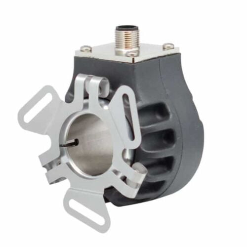
5mm Opto-ASIC encoder with a low profile (50.8mm)
Imperial bore sizes range from 0.625” to 1.125”
Metric bore sizes ranging from 6 mm to 28 mm
Single replacement solution for 50.8mm to 88.9mm encoders
Resolutions to 10,000 PPR, frequencies to 1 MHz
Versatile flexible mounting options
RoHS compliant
Corrosion-Resistant Option
Features
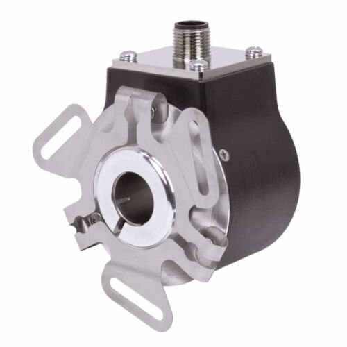
58 mm package available in thru-bore or hollow bore
Resolutions from 1 to 65,536 PPR
6 different output types to choose from
32 different waveforms available
Standard and Metric Bore Sizes up to 5/8” and 15 mm
Several Flexible Mounting Options
IP67 Sealing Available
Features
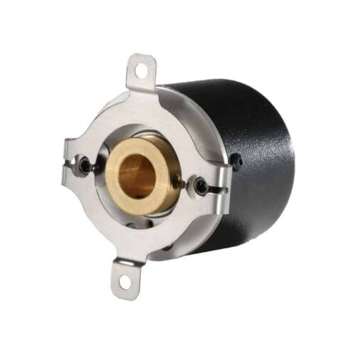
Miniature size (38.1mm diameter)
Up to 30,000 PPR
Flex mounting & large hollow bore option (Up to 14mm)
High-temperature option
Features
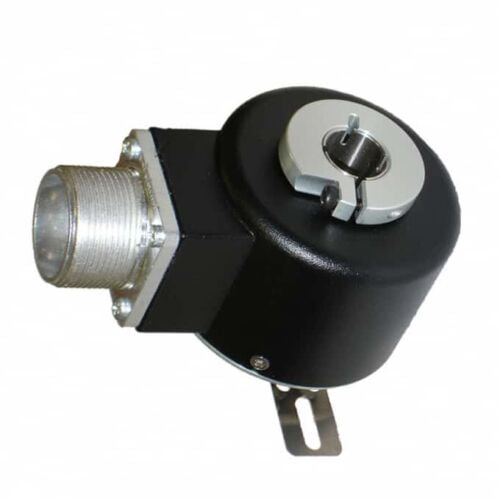
Size 25 / 63.5mm Diameter (Hollow Shaft)
Up to 12 Pole Commutation Available
Thru Bore and Blind Bore Options
Simple, Innovative Flexible Mounting System
Incorporates Opto-ASIC Technology
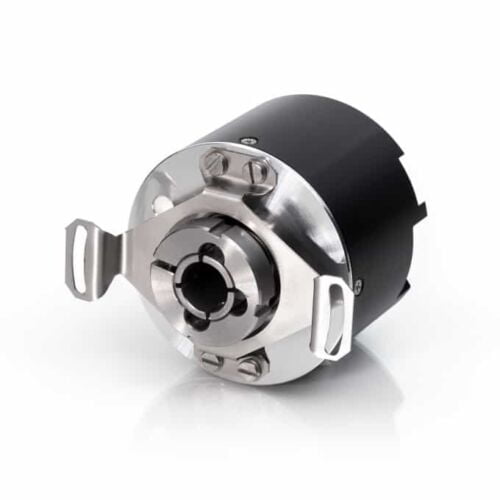
Features
Number of output pulses per revolution 100-108000 ppr
Maximum shaft speed 10000 rpm
Permissible motion of shaft - axial: ± 0.5 mm- radial: ± 0.05 mm
Accuracy (T1-period lines on disc in arc. sec) ± 0.1T1 arc. sec
Starting torque at 20°C ≤ 0.025 Nm
Rotor moment of inertia < 1.5x10⁻⁴ kgm2
Protection (housing) (IEC 529) IP64
Protection (shaft side) (IEC 529) IP64
Maximum weight without cable 0.3 kg
Operating temperature -10...+70°C
Storage temperature -30...+80°C
Maximum humidity (non-condensing) 98%
Permissible vibration (55 to 2000 Hz) ≤ 100 m/s²
Permissible shock (5 ms) ≤ 1000 m/s²
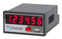
Features
Scalable 14-bit analog input for 0 ... 10 V or 0/4 ... 20 mA
Power supply 24 VDC
Miniature norm panel housing
5 digits LED display with 8 mm height
Display range -19999 ... 99999, adjustable zero and full-scale value
Latch input to freeze the display, minimum/maximum record memory
Easy to set up with only two front keys and menu support
Delivery includes adapter frame for 50 x 25 mm cut out and label set with dimensions
Front dimension 48 x 24 x 59 mm (1.89 x 0.945 x 2.322")
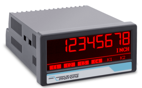
Features
2 universal 16-bit analogue inputs for ±10 V or 0/4 … 20 mA
3 control inputs for HTL / PNP signals
Power supply 18 ... 30 VDC
24 V auxiliary output for encoder supply
High accuracy reference output 10 V for potentiometers > 1 kOhm
3.78 x 1.89-inch norm panel housing and IP65 protection
Bright and high-contrast display with event-dependent color variations
Emulation of a 7-segment display inclusively icons and units
Intuitive and easy parameterization by plain text and touchscreen
Operating modes for visualization of INPUT 1, INPUT 2 or combinations of IN1 + IN2, IN1 - IN2, IN1 x IN2, IN1: IN2
Numerous features, e. g. tara, filters, averaging
Linearization with 24 control points
Options
Option AC: Power supply 115 ... 230 VAC
Option AO: 16-bit analog output, 4 control outputs, serial RS232 interface
Option AR: 16-bit analog output, 4 control outputs, serial RS485 interface
Option CO: 4 control outputs, serial RS232 interface
Option CR: 4 control outputs, serial RS485 interface
Option RL: 2 relay outputs
Option IO: IO-Link Device V1.1
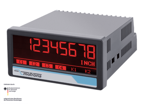
Features
2 universal 16-bit analog inputs for ±10 V or 0/4 … 20 mA
3 control inputs for HTL / PNP signals
Power supply 18 ... 30 VDC
24 V auxiliary output for encoder supply
High accuracy reference output 10 V for potentiometers > 1 kOhm
3.78 x 1.89-inch norm panel housing and IP65 protection
Bright and high-contrast display with event-dependent color variations
Emulation of a 7-segment display inclusively icons and units
Intuitive and easy parameterization by plain text and touchscreen
Operating modes for visualization of INPUT 1, INPUT 2 or combinations of IN1 + IN2, IN1 - IN2, IN1 x IN2, IN1: IN2
Numerous features, e. g. Ttara, filters, averaging
Linearization with 24 control points
Option IO (= IO-Link Device)
Data transfer via COM3 (230,4 kBaud)
Cycle times < 3 msec
Process data IN 32 Byte (6 x process values from AX350):
- Analog value 1 (scaled / linearized) and unit
- Analog value 2 (scaled / linearized) and unit
- Analog value 1 (scaled / linearized) with totalisation and unit
- Analog value 2 (scaled / linearized) with totalisation and unit
- Shortcut analogue value 1 (scaled / linearized) with analogue value 2 (scaled / linearized) and unit
- Shortcut totalisator analogue value 1 (scaled / linearized) with totalisator analogue value 2 (scaled / linearized) and unit
Process data Out 8 Byte (2 x IO-Link process values to AX350):
- IOL process value Out 1 with scaling, adjustable decimal point and programmable units
- IOL process values Out 2 with scaling, adjustable decimal point and programmable units
Combinable with further options:
Option AC: Power supply 115 ... 230 VAC
Option AO: 16-bit analog output, 4 control outputs, serial RS232 interface
Option AR: 16-bit analog output, 4 control outputs, serial RS485 interface
Option CO: 4 control outputs, serial RS232 interface
Option CR: 4 control outputs, serial RS485 interface
Option RL: 2 relay outputs
Features
6-wire connection for one strain gauge full bridge sensor
4 control inputs [HTL/PNP]
1 analog output ±10 V, 0/4 ... 20 mA, 16 bit
4 control outputs for signalling different operation states
Power supply 18 ... 30 VDC
Functions for scaling and linking the sensor signals (e.g. A+B, A-B, ...)
Adjustable bridge voltage per sensor from 3 VDC ... 10 VDC
Sensitivity of the sensor inputs 1 ... 10 mV
Transmission of the sensor data via RS485
Programming via USB and the user interface OS (freeware)
Protection class IP20
Compact housing for mounting on 35 mm top-hat rail (according to EN 60715)
Features
6-wire connection for two independent strain gauge full bridge sensors
4 control inputs [HTL/PNP]
2 independent analog outputs ±10 V, 0/4 ... 20 mA, 16 bit
4 control outputs for signalling different operation states
Power supply 18 ... 30 VDC
Functions for scaling and linking the sensor signals (e.g. A+B, A-B, ...)
Adjustable bridge voltage per sensor from 3 VDC ... 10 VDC
Sensitivity of the sensor inputs 1 ... 10 mV
Transmission of the sensor data via RS485
Programming via USB and the user interface OS (freeware)
Protection class IP20
Compact housing for mounting on 35 mm top-hat rail (according to EN 60715)
Features
2 pulse inputs with format A, B, Z [HTL] or A, /A, B, /B, Z, /Z [RS422]
Input frequency up to 250 kHz for asymmetrical and up to 1 MHz for symmetric signals
2 control inputs for HTL / PNP signals [10 ... 30 VDC]
2 output channels with format A, B, Z [HTL] or A, /A, B, /B, Z, /Z [RS422], each output adjustable separately
Power supply 12 ... 30 VDC
Snap-on housing for top-hat rail (according to EN 60715)
Features
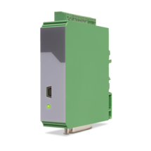
1 Strain gauge input
3 VDC and 10 VDC bridge voltage per sensor connection
1 … 10 mV sensitivity
optionally 3 control inputs for PNP signals [10 ... 30 VDC]
IO link interface
Power supply 12 ... 30 VDC
Compact housing for mounting on 35 mm DIN rail (according to EN 60715)
Features
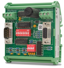
Pulse input in format A, /A, B, /B, Z, /Z [RS422, HTL]
Pulse input in format A, B, Z [HTL]
Input frequency up to 1 MHz
Pulse output in format A, /A, B, /B, Z, /Z [RS422, HTL]
Pulse output in format A, B, Z [HTL]
Power supply 9 ... 30 VDC
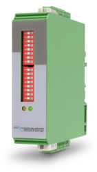
Settings via DIL switches
Level conversion (RS422, HTL single-ended, HTL differential, TTL and vice versa)
Division of two-track A / B pulses with adjustable ratio 1: 1 to 1: 4096
Division of the Z pulse with adjustable ratio 1: 1 to 1: 256
External HTL signals for various functions
Implementation between the two types of representations for the direction of rotation (A / B 90 °, A/B Dir and vice versa, Division possible)
Snap-on housing for top-hat rail (acc. EN 60715)
Dimension (B x H X T) 22,5 x 102 x 102 mm
Features
4 independent input channels with format A, B, C, D [HTL] or A, /A, B, /B, C, /C, D, /D [RS422], also possible for single-channel
4 output channels with format A, B, C, D [HTL] or A, /A, B, /B, C, /C, D, /D [RS422]
Maximum input frequency 1 MHz
Very short conversion time < 300 ns
Optical wavelength 1300 nm
Transmission distance up to 3000 meters
Power supply 5 VDC (for LW213)
Power supply 10 ... 30 VDC (for LW213-1, LW213-2, LW213-3)
Snap-on housing for top-hat rail (according to EN 60715)
Pre-configured optical fibres are available
Features
4 independent input channels with format A, B, C, D [HTL] or A, /A, B, /B, C, /C, D, /D [RS422], also possible for single channel
4 output channels with format A, B, C, D [HTL] or A, /A, B, /B, C, /C, D, /D [RS422]
Maximum input frequency 1 MHz
Very short conversion time < 300 ns
Optical wavelength 1300 nm
Transmission distances up to 3000 meters
Power supply 5 VDC (for LW214)
Power supply 10 ... 30 VDC (for LW214-1, LW214-2)
Snap-on housing for top-hat rail (according to EN 60715)
Pre-configured optical fibers are available
Features
4 independent input channels with format A, B, C, D [HTL] or A, /A, B, /B, C, /C, D, /D [RS422], also possible for single channel
4 output channels with format A, B, C, D [HTL] or A, /A, B, /B, C, /C, D, /D [RS422]
Maximum input frequency 1 MHz
Very short conversion time < 300 ns
Optical wavelength 850 nm
Transmission distance up to 2000 meters
Power supply 5 VDC (for LW215)
Power supply 10 ... 30 VDC (for LW215-1, LW215-2, LW216-3)
Snap-on housing for top-hat rail (according to EN 60715)
Pre-configured optical fibers are available
Features
4 independent input channels with format A, B, C, D [HTL] or A, /A, B, /B, C, /C, D, /D [RS422], also possible for single channel
4 output channels with format A, B, C, D [HTL] or A, /A, B, /B, C, /C, D, /D [RS422]
Maximum input frequency 1 MHz
Very short conversion time < 300 ns
Optical wavelength 850 nm
Transmission distance up to 2000 meters
Power supply 5 VDC (for LW216)
Power supply 10 ... 30 VDC (for LW216-1, LW216-2)
Snap-on housing for top-hat rail (according to EN 60715)
Pre-configured optical fibers are available
Features
1 SSI input / output channel [RS422] with format DATA+, DATA-, CLOCK+, CLOCK-
1 Error input (LW217) resp. 1 open-drain-output (LW218)
Maximum input frequency 1 MHz
Very short conversion time < 300 nsec.
Optical wavelength 850 nm
Transmission distance up to 2000 meters
Power supply 5 VDC (for LW217)
Power supply 10 ... 30 VDC (for LW217-1)
Free adjustable SSI resolution from 1 ... 99 bit
Snap-on housing for top-hat rail (according to EN 60715)
Pre-configured optical fibres are available
Features
1 SSI input / output channel [RS422] with format DATA+, DATA-, CLOCK+, CLOCK-
1 open-drain-output (LW218)
Maximum input frequency 1 MHz
Very short conversion time < 300 ns
Optical wavelength 1300 nm
Transmission distance up to 2000 meters
Power supply 5 VDC (for LW218)
Power supply 10 ... 30 VDC (for LW218-1)
Free adjustable SSI resolution from 1 ... 99 bit
Snap-on housing for top-hat rail (according to EN 60715)
Glass fibre cables are available ready-assembled
Features
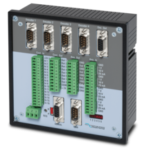
4 pulse inputs with format A, /A, B, /B [RS422]
4 scalable 12-bit analog inputs for ±10 V or 0/4 ... 20 mA
8 control inputs for PNP signals [10 ... 30 VDC]
4 scalable 12-bit analog outputs for ±10 V or 0/4 ... 20 mA
Short loop time (depending on application)
Power supply 18 ... 35 VDC
Snap-on housing for top-hat rail (according to EN 60715)
Setup via Windows operator software (free of charge)
OnBoard interfaces: RS232 and CANopen
Features
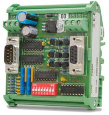
Start-stop interface for absolute transducers and magnetostrictive sensors
SSI input in the format DATA +, DATA-, CLOCK +, CLOCK- up to 32 bits
3 control inputs (hold) for PNP signals [10 ... 30 VDC]
Pulse inputs A, B [HTL], A, / A, B, / B [RS422, HTL]
Input frequency up to 1 MHz
25-bit parallel output push-pull in BCD, binary or Gray code format
Power supply 18 ... 30 VDC
Compact housing for mounting on 35 mm top-hat rail (according to EN 60715)
Features
Pulse input with format A, B, Z [HTL] (10 ... 30 V)
Input frequency max. 200 kHz
Pulse output with format A, /A, B, /B, Z, /Z [RS422 / TTL]
Power supply 5 VDC
Converts HTL levels (A / B / Z) in TTL / RS422, incl. the inverted signals
Converts also static/separate directional information into a dual channel A / B signal with a 90° phase shift
Open print version with plastic snap-on housing for top-hat rail (according to EN 60715)
Features
Pulse input with format A, /A, B, /B, Z, /Z [TTL / RS422]
Input frequency max. 200 kHz
Pulse output with format A, B, Z [HTL]
Power supply 10 ... 30 VDC
Converts TTL / RS422 signals (A, /A, B, /B, Z, /Z) in HTL format with an output level of 10 ... 30 VDC
Generates additionally an A / B directional information with 90° phase shift‚ a static HIGH / LOW directional signal or separate directional pulses
Open print version with plastic snap-on housing for top-hat rail (according to EN 60715)
Features
1 pulse input with format A, B, Z [HTL] or A, /A, B, /B, Z, /Z [RS422]
Input frequency up to 500 kHz
1 pulse output with format A, /A, B, /B, Z, /Z [RS422, HTL]
Power supply 5 ... 30 VDC
Potential separation between input and output
Possibility to convert A, B / 90 ° directional information into static directional signal and vice versa
Connections on the input as well as on the output either via sub-D plugs or plug-in screw terminals (parallel connections)
Snap-on housing for top-hat rail (according to EN 60715)
Features
Start-stop interface for absolute transducers and magnetostrictive sensors
Adjustable frequency of the init pulses from 62.5 Hz to 5 kHz
Analog output ± 10 V, 0/4 ... 20 mA, 16 bit
Power supply 18 ... 30 VDC
Compact housing for mounting on a 35 mm top-hat rail (according to EN 60715)
Simple parameterization via the OS6.0 user interface
Serial RS232 / RS485 interface
Pulse inputs A, B [HTL], A, /A, B, /B [RS422, HTL]
SSI input DATA+, DATA-, CLOCK+, CLOCK- [RS422], 32 Bit
USB interface and RS232/RS485 interface for configuration and serial readout
Page load link