Skip to content
Features
Number of output pulses per revolution 18000-1800000 ppr
Line number on disc (z) 18000
Reference signal - standard: 1 per shaft revolution
- distance coded: 36 per shaft revolution
Maximum shaft speed 5000 rpm
Maximum shaft load
- radial: 10 N
Accuracy ± 7.5 arc. sec; ± 5.0 arc. sec
Starting torque at 20°C ≤ 0.01 Nm
Rotor moment of inertia < 20x10-6 kgm2
Protection (IEC 529) IP64
Maximum weight without cable 0.7 kg
Operating temperature 0...+50°C
Storage temperature -30...+80°C
Maximum humidity (non-condensing) 98%
Permissible vibration (55 to 2000 Hz) ≤ 100 m/s²
Permissible shock (11 ms) ≤ 300m/s²
Features
Number of output pulses per revolution 18000-1800000 ppr
Line number on disc (z) 18000; 36000
Reference signal
- standard: 1 per shaft revolution
- distance coded for z = 18000: 36 per shaft revolution
- distance coded for z = 36000: 72 per shaft revolution
Permissible mech. speed ≤ 1000 rpm
Max. operating speed 300 to 500 rpm
Accuracy ± 2.5 arc. sec
Permissible shaft load - axial: ≤ 30 N
- radial: ≤ 30 N
Starting torque at 20°C ≤ 0.012 Nm
Rotor moment of inertia < 3.7x10⁻⁴ kgm2
Protection (IEC 529) IP64
Maximum weight without cable 3.5 kg
Operating temperature 0...+70°C
Storage temperature -30...+85°C
Maximum humidity (non-condensing) 98%
Permissible vibration (55 to 2000 Hz) ≤ 100 m/s²
Permissible shock (11 ms) ≤ 300m/s²
Features
Number of output pulses per revolution 18000-1800000 ppr
Line number on disc (z) 18000; 36000
Reference signal
- standard: 1 per shaft revolution
- distance coded for z = 18000: 36 per shaft revolution
- distance coded for z = 36000: 72 per shaft revolution
Permissible mech. speed ≤ 1000 rpm
Max. operating speed 300 to 500 rpm
Accuracy ± 2.5 arc. sec
Permissible shaft load - axial: 0.02 mm
- radial: 0.02 mm
Starting torque at 20°C ≤ 0.012 Nm
Rotor moment of inertia < 3.7x10⁻⁴ kgm2
Protection (IEC 529) IP64
Maximum weight without cable 4.1 kg
Operating temperature 0...+70°C
Storage temperature -30...+85°C
Maximum humidity (non-condensing) 98%
Permissible vibration (55 to 2000 Hz) ≤ 100 m/s²
Permissible shock (11 ms) ≤ 300m/s²
Features
Number of output pulses per revolution 3.600.000
Line number on disc (z) 36000
Reference signal
- 1 per shaft revolution
- 36 per shaft revolution
- 72 per shaft revolution
Permissible mech. speed ≤ 1000 rpm
Max. operating speed 300 to 500 rpm
Accuracy ± 2.0 arc. sec
Permissible shaft load - axial: 0.02 mm
- radial: 0.02 mm
Starting torque at 20°C ≤ 0.5 Nm
Rotor moment of inertia < 0.9x10⁻³ kgm2
Protection (IEC 529) IP64
Maximum weight without cable 4.5 kg
Operating temperature 0...+70°C
Storage temperature -30...+85°C
Maximum humidity (non-condensing) 98%
Permissible vibration (55 to 2000 Hz) ≤ 100 m/s²
Permissible shock (11 ms) ≤ 300m/s²
Features
Number of output pulses per revolution 18000-1800000 ppr
Line number on disc (z) 18000
Reference signal - standard: 1 per shaft revolution
- distance coded: 36 per shaft revolution
Permissible mech. speed ≤ 3000 rpm
Max. operating speed 600 to 1000 rpm
Accuracy grades ± 5.0 arc. sec
Permissible shaft runout - axial: 0.02 mm
- radial: ± 0.02 mm
Starting torque at 20°C ≤ 0.08 Nm
Rotor moment of inertia < 0.6x10⁻⁴ kgm2
Protection (IEC 529) IP64
Maximum weight without cable 1.2 kg
Operating temperature 0...+70°C
Storage temperature -30...+85°C
Maximum humidity (non-condensing) 98%
Permissible vibration (55 to 2000 Hz) ≤ 100 m/s²
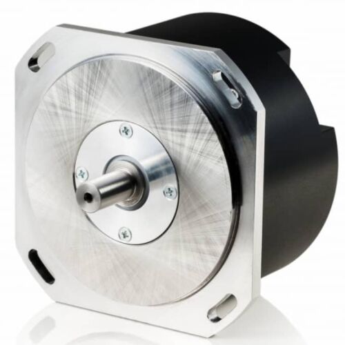
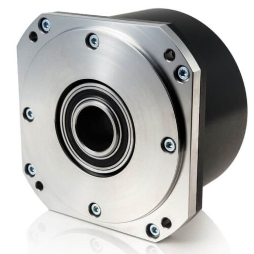
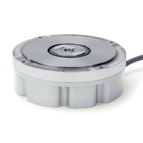
Features
Absolute measuring method
Hollow shaft diameter (up to 50 mm)
Integrated stator coupling
Simple installation
Typical field of application
Rotational axes with reduced accuracy requirements
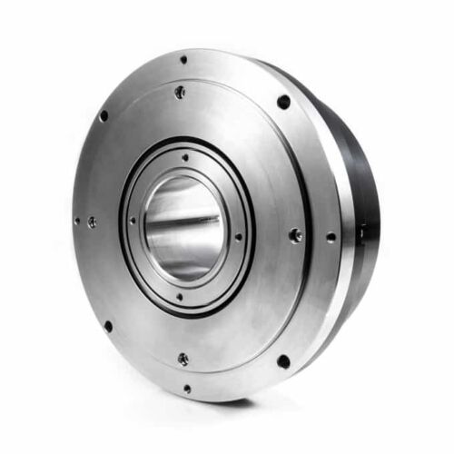
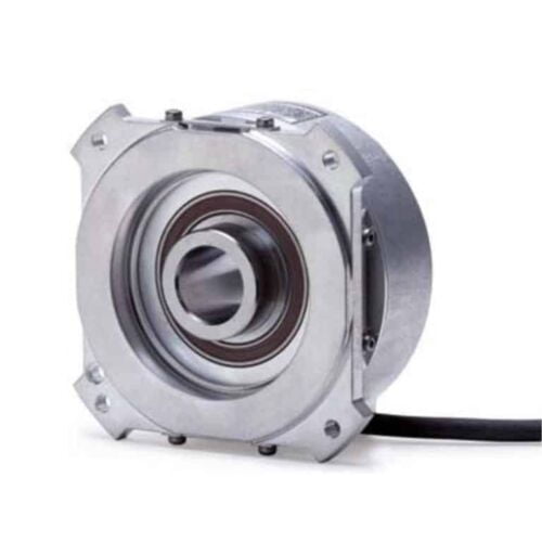
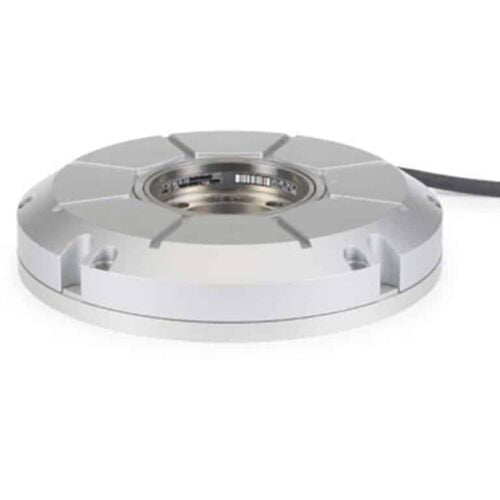
Features
Absolute measuring method
Large hollow shaft diameter (up to 100 mm)
Integrated stator coupling
Compact size for limited installation space
System accuracy includes the deviation caused by the shaft connection
Outstanding dynamic response
Simple installation
Typical field of application
Rotary tables
Swivel heads
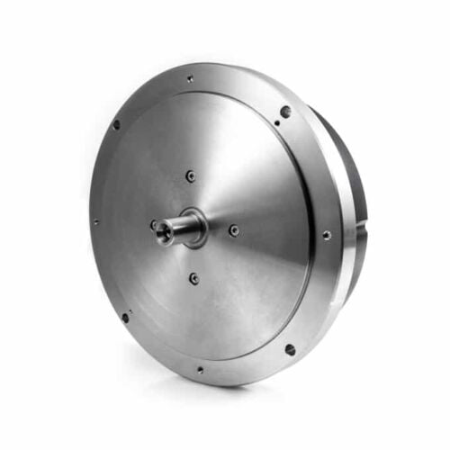
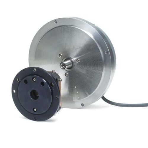
Features
Incremental measuring method
Solid shaft
Separate shaft coupling for large mounting tolerances
System accuracy does not include the deviation caused by the shaft connection
Typical field of application
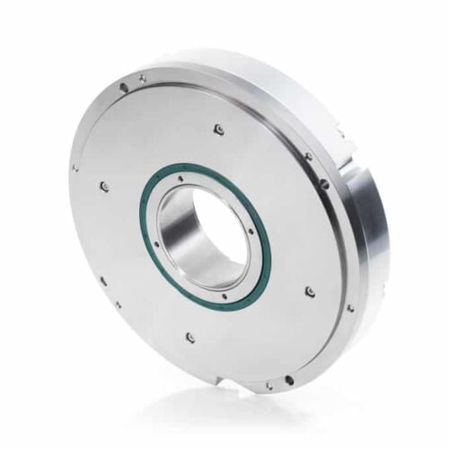
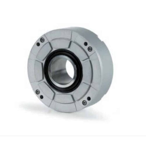
Features
Incremental measuring method
Large hollow shaft diameter (up to 60 mm)
Integrated stator coupling
Compact size for limited installation space
System accuracy includes the deviation caused by the shaft connection
Outstanding dynamic response
Simple installation
Typical field of application
Rotary tables
Swivel heads
Features
Large hollow shaft diameter (up to 10 m with a scale tape)
High shaft speeds up to 20,000 rpm
No additional starting torque from shaft seals
Segment versions
Also available with Functional Safety Modular angle encoders with optical scanning are available with various graduation carriers:
ERP/ERO: Glass circular scale with hub
ERA/ECA 4000: Steel drum
ERA 7000/8000: Steel scale tape
Typical field of application
High-resolution rotary axes with high reproducibility
Very high number of signal periods
Small mounting space
Small interpolation error and low signal noise
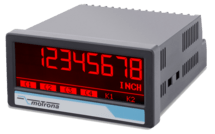
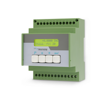
Features
Pulse input with format A, B, 90° [HTL], single channel as an option
HTL inputs for encoder and sensors with NPN / PNP or NAMUR switching characteristics
Input frequency up to 250 kHz
3 control inputs for HTL / PNP signals
Power supply 18 ... 30 VDC
24 V auxiliary output for encoder supply
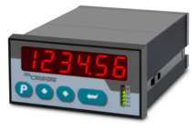
3.78 x 1.89-inch norm panel housing and IP65 protection
Bright and high-contrast display with event-dependent color variations
Emulation of a 7-segment display inclusively icons and units
Intuitive and easy parameterization by plain text and touchscreen
Multi-functional device for speed, position, timer, counter or velocity application
Operating modes such as scaling, average filter, start-up suppression
Linearization with 24 control points
Options
Option AC: Power supply 115 ... 230 VAC
Option AO: 16-bit analog output, 4 control outputs, serial RS232 interface
Option AR: 16-bit analog output, 4 control outputs, serial RS485 interface
Option CO: 4 control outputs, serial RS232 interface
Option CR: 4 control outputs, serial RS485 interface
Option RL: 2 relay outputs
Options can be combined.
Features
2 Incremental inputs with format A, /A, B, /B
Differential, single-ended HTL / RS422
Input frequency up to 1 MHz
Power supply 18 ... 30 VDC
5 / 24 VDC auxiliary output for encoder supply
3.78 x 1.89-inch norm panel housing and IP65 protection
Bright and high-contrast display with event-dependent color variations
Emulation of a 7-segment display inclusively icons and units
Intuitive and easy parameterization by plain text and touchscreen
Multi-functional device for speed, process time, timer, counter or velocity application
Operating modes such as scaling, average filter, start-up suppression
Linearization with 24 control points
Options
Option AC: Power supply 115 ... 230 VAC
Option AO: 16-bit analog output, 4 control outputs, serial RS232 interface
Option AR: 16-bit analog output, 4 control outputs, serial RS485 interface
Option CO: 4 control outputs, serial RS232 interface
Option CR: 4 control outputs, serial RS485 interface
Option RL: 2 relay outputsOptions can be combined.
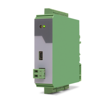
Features
Pulse input with format A, B, Z [HTL single-ended, TTL single-ended] or A, /A, B, /B, Z, /Z [RS422, HTL differential]
4 control inputs for HTL, PNP signals [10 ... 30 VDC]
Input and output frequency up to 1 MHz
3 incremental outputs with format A, /A, B, /B, Z, /Z, Push-Pull, [8 … 29 VDC]
Power supply 9 ... 30 VDC
Snap-on housing for top-hat rail (acc. EN 60715)
Multiplier/divisor adjustable as quotient F1 / F2
Multiplication/division without cumulative residual errors
Additional functions such as jog, trim, offset and reference
Features
Pulse input with format A, B, 90° [HTL] or A, /A, B, /B, Z, /Z [RS422]
4 control inputs for PNP signals [10 ... 30 VDC]
Input and output frequency up to 1 MHz
Pulse output with format A, /A, B, /B, Z, /Z and
push-pull characteristic, [5 ... 30 VDC]
Power supply 11 ... 30 VDC
Snap-on housing for top-hat rail (according to EN 60715)
LCD backlighted
Setup via keys, RS232
The device multiplies an incoming frequency by a proportional factor F1 and a reciprocal factor F2. The two factors F1 and F2 are adjustable in the range of 0.0005 to 9.9999
All operation modes provide error-free frequency conversion, with full consideration of the A / B phase and direction of the quadrature signals, therefore no cumulative errors, even with continuous changes of directions and vibrations
Zero pulse generator: the frequency multiplier generates at the output an index signal with an adjustable pulse interval, which can be synchronized as needed with the zero pulse at the input
Features
Frequency inputs A, B [HTL], A, / A, B, / B [RS422, HTL]
3 control inputs (hold) for PNP signals [10 ... 30 VDC]
SSI input in the format DATA +, DATA-, CLOCK +, CLOCK- up to 32 bits
Start-stop interface for absolute transducers and magnetostrictive sensors
Input frequency up to 1 MHz
25-bit parallel output push-pull in BCD, binary or Gray code format
Power supply 18 ... 30 VDC
Compact housing for mounting on 35 mm top-hat rail (according to EN 60715)
Features
Pulse inputs A, B [HTL], A, /A, B, /B [RS422, HTL]
Input frequency up to 1 MHz [RS422], 200 kHz [HTL]
Analog output ±10 V or 0/4 ... 20 mA, 16 Bit
Power supply 18 ... 30 VDC
Snap-on housing for top-hat rail (according to EN 60715)
Setup via operator software OS6.0
Serial RS232- / RS485 interface
SSI input DATA+, DATA-, CLOCK+, CLOCK- [RS422], 32 Bit
Start-stop interface for absolute transducers and magnetostrictive sensors
USB interface and RS232/RS485 interface for configuration and serial readout
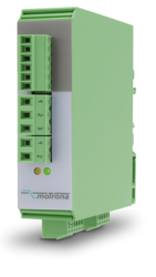
Features
Control input with format [HTL]
2 SSI inputs with format [RS422]
Cutt-off frequency 100 kHz ... 1 MHz
2 encoder inputs, short-circuit-proof
1 SSI output with format [RS422]
Power supply 12 ... 30 V DC
Current consumption (unloaded) 50 mA
Encoder supply 2 x 125mA (Vin – 2 V) short-circuit-proof
Delay / Output / Input100 ns
Operation temperature : 0 ... 45 °C (32 ... 113 °F)
SSI pause time min. 25 ns
Switching time is synchronized automatically with the next SSI break
Cascadable for more SSI encoders
All connections via pluggable screw terminal block
Snap-on housing for top-hat rail (according to EN 60715)
LEDs for indication of the input pulses
Dimension W x H x D = 22,5 x 121 x 112 mm (8.86 x 47.64 x 44.09'')
Plastic housing incl. plug
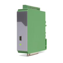
Features
1 incremental input (A, /A, B, /B)
for HTL/TTL/RS422 for NPN/PNP/NAMUR encoders and sensors
optionally 3 control inputs for PNP signals [10 ... 30 VDC]
IO link interface
Power supply 12 ... 30 VDC
Compact housing for mounting on 35 mm DIN rail (according to EN 60715)
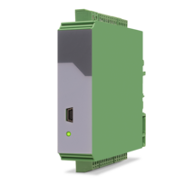
Features
1 SSI input (10 … 32 bit)
for single-turn and multiturn encoders
optionally 3 control inputs for PNP signals [10 ... 30 VDC]
IO link interface
Power supply 12 ... 30 VDC
Compact housing for mounting on 35 mm DIN rail (according to EN 60715)
Features
SSI input with format DATA+, DATA-, CLOCK+, CLOCK- up to 32 Bit
Impulse inputs A, B [HTL], A, /A, B, /B [RS422, HTL]
3 control inputs (Hold) for PNP signals [10 ... 30 VDC]
Start-stop interface for absolute transducers and magnetostrictive sensors
Input frequency up to 1 MHz
25-bit parallel output push-pull in BCD, binary or Gray code format
Power supply 18 ... 30 VDC
Compact housing for mounting on 35 mm top-hat rail (according to EN 60715)
Features
Pulse input in format A, /A, B, /B, Z, /Z [RS422, HTL]
Pulse input in format A, B, Z [HTL]
Input frequency up to 1 MHz
Pulse output in format A, /A, B, /B, Z, /Z [RS422, HTL]
Pulse output in format A, B, Z [HTL]
Power supply 9 ... 30 VDC
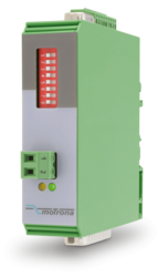
Settings via DIL switches
Level conversion (RS422, HTL single-ended, HTL differential, TTL and vice versa)
Division of two-track A / B pulses with adjustable ratio 1: 1 to 1: 4096
Division of the Z pulse with adjustable ratio 1: 1 to 1: 256
External HTL signals for various functions
Implementation between the two types of representations for the direction of rotation (A / B 90 °, A/B Dir and vice versa, Division possible)
Snap-on housing for top-hat rail (acc. EN 60715)
Dimension (B x H X T) 22,5 x 102 x 102 mm
Features
SSI input DATA+, DATA-, CLOCK+, CLOCK- [RS422], 32 Bit
SSI clock frequency up to 1 MHz
Analog output ±10 V or 0/4 ... 20 mA, 16 Bit
Power supply 18 ... 30 VDC
Snap-on housing for top-hat rail (according to EN 60715)
Setup via operator software OS6.0
Serial RS232- / RS485 interface
Pulse inputs A, B [HTL], A, /A, B, /B [RS422, HTL]
Start-stop interface for absolute transducers and magnetostrictive sensors
USB interface and RS232/RS485 interface for configuration and serial readout
Features
Start-stop interface for absolute transducers and magnetostrictive sensors
SSI input in the format DATA +, DATA-, CLOCK +, CLOCK- up to 32 bits
3 control inputs (hold) for PNP signals [10 ... 30 VDC]
Pulse inputs A, B [HTL], A, / A, B, / B [RS422, HTL]
Input frequency up to 1 MHz
25-bit parallel output push-pull in BCD, binary or Gray code format
Power supply 18 ... 30 VDC
Compact housing for mounting on 35 mm top-hat rail (according to EN 60715)
Features
20-bit parallel input with format BCD, binary or Gray-Code
Input frequency: fast encoder 5 kHz, auto-transmit / data logging 0.5 kHz
4 status outputs, with push-pull characteristics, short-circuit-proof [5 ... 30 VDC]
Power supply 10 ... 30 VDC
Snap-on housing for top-hat rail (according to EN 60715)
Serial RS232 / RS485 interface
Features
2 pulse inputs with format A, B, 90° [HTL] or A, /A, B, /B [RS422]
4 control inputs for HTL / PNP / NPN / Namur signals [10 ... 30 VDC]
Input frequency up to 300 kHz
4 fast transistor outputs, push-pull, short-circuit-proof [5 … 30 VDC]
1 scalable 14-bit analog output (±10 V or 0/4 … 20 mA)
Loop time approx. 250 µs
Defining incremental dimensions via keyboard
Power supply 24 VAC and 17 … 40 VDC
Compact norm panel housing (according to EN 60715)
Top hat rail mounting by using SM300 support brackets (option)
Setup via keys or via PC by serial RS232 interface
PROFIBUS connection via mMotrona gateway PB251
Page load link