Skip to content
-
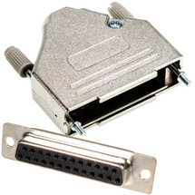
Features
- Solder connection
- Metallised plastic enclosure
- Mounting screws included
-
Features
- Solder connection
- Metallised plastic enclosure
- Mounting screws included
-
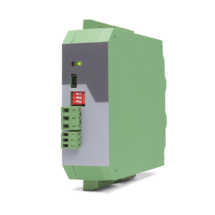
Features
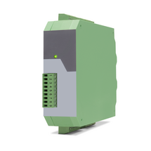
- 6-wire connection for one strain gauge full bridge sensor
- 4 control inputs [HTL/PNP]
- 1 analog output ±10 V, 0/4 ... 20 mA, 16 bit
- 4 control outputs for signalling different operation states
- Power supply 18 ... 30 VDC
- Functions for scaling and linking the sensor signals (e.g. A+B, A-B, ...)
- Adjustable bridge voltage per sensor from 3 VDC ... 10 VDC
- Sensitivity of the sensor inputs 1 ... 10 mV
- Transmission of the sensor data via RS485
- Programming via USB and the user interface OS (freeware)
- Protection class IP20
- Compact housing for mounting on 35 mm top-hat rail (according to EN 60715)
-
Features
- 6-wire connection for two independent strain gauge full bridge sensors
- 4 control inputs [HTL/PNP]
- 2 independent analog outputs ±10 V, 0/4 ... 20 mA, 16 bit
- 4 control outputs for signalling different operation states
- Power supply 18 ... 30 VDC
- Functions for scaling and linking the sensor signals (e.g. A+B, A-B, ...)
- Adjustable bridge voltage per sensor from 3 VDC ... 10 VDC
- Sensitivity of the sensor inputs 1 ... 10 mV
- Transmission of the sensor data via RS485
- Programming via USB and the user interface OS (freeware)
- Protection class IP20
- Compact housing for mounting on 35 mm top-hat rail (according to EN 60715)
-
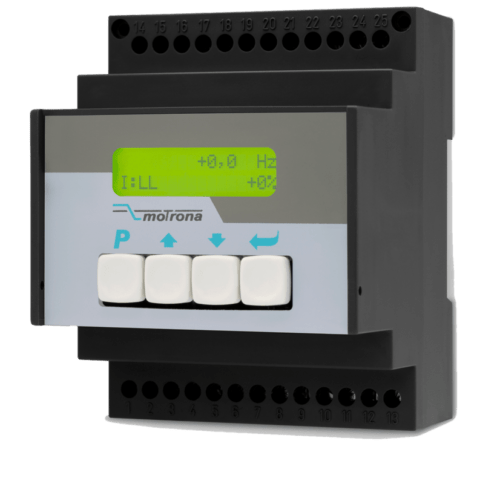
Features
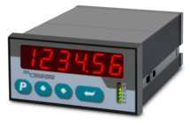
- Strain gauge input, 6-wire connection
- Input pt100 and thermocouples (J and K)
- 3 control inputs for HTL / PNP signals
- Power supply 18 ... 30 VDC
- Adjustable bridge voltage 3 VDC to 10 VDC
- 1 … 10 mV sensitivity
- Standard installation housing with 96 x 48 mm and protection class IP65
- Bright and high-contrast graphic display with event-dependent color variants
- Emulation of a 7-segment display with symbols and units
- Intuitive and simple parameterization through plain text and touchscreen
- Numerous functions such as tare, filter, averaging
- Linearization with 24 support points
Options
- Option AC: Power supply 115 ... 230 VAC
- Option AO: 16-bit analog output, 4 control outputs, serial RS232 interface
- Option AR: 16-bit analog output, 4 control outputs, serial RS485 interface
- Option CO: 4 control outputs, serial RS232 interface
- Option CR: 4 control outputs, serial RS485 interface
- Option RL: 2 relay outputs
- Option IO: IO-Link Device V1.1
Options can be combined.
-
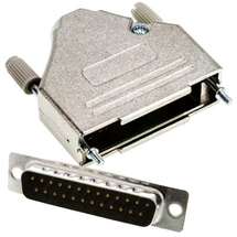
Features
- Solder connection
- Metallised plastic enclosure
- Mounting screws included
-
Features
- Solder connection
- Metallised plastic enclosure
- Mounting screws included
-
Features
- Pulse input with format A, B, 90° [HTL] or A, /A, B, /B [RS422], also possible for single-channel
- Input frequency up to 500 kHz
- 2 output relays with potential-free change-over contact (forward, reward and zero motion)
- 2 transistor outputs with High-Side-Driver, short-circuit-proof
- Power supply 17 ... 30 VDC
- Snap-on housing for top hat rail (according to EN 60715)
- DIL switch for setup of input characteristic and definition of standstill
-
Features
- Pulse input with format A, B, 90° [HTL] or A, /A, B, /B [RS422], also possible for single-channel
- Input frequency up to 1 MHz
- 3 output relays
- 14 Bit analog output for ±10 V or 0/4 ... 20 mA
- Power supply 17 ... 30 VDC
- Auxiliary voltage output +5 V for the supply of TTL encoders
- Snap-on housing for top hat rail (according to EN 60715)
- LCD display, backlighted
- Setup via keys or via PC by serial RS232 interface
-
Features
- Pulse input with format A, B, 90° [HTL] or A, /A, B, /B [RS422], also possible for single-channel
- Input frequency up to 1 MHz
- 3 fast transistor switching outputs [PNP]
- 14 bit analog output for ±10 V or 0/4 ... 20 mA
- Power supply 17 ... 30 VDC
- Auxiliary voltage output +5 V for the supply of TTL encoders
- Snap-on housing for top hat rail (according to EN 60715)
- LCD display, backlighted
- Setup via keys or via PC by serial RS232 interface
-
Features
- Pulse input with format A, B, 90° [HTL] or A, /A, B, /B [RS422], also possible for single-channel
- Input frequency up to 1 MHz
- 3 output relays
- Power supply 17 ... 30 VDC
- Auxiliary voltage output +5 V for the supply of TTL encoders
- Snap-on housing for top hat rail (according to EN 60715)
- LCD display, backlighted
- Setup via keys or via PC by serial RS232 interface
-
Features
- 1 Strain gauge input
- 3 VDC and 10 VDC bridge voltage per sensor connection
- 1 … 10 mV sensitivity
- optionally 3 control inputs for PNP signals [10 ... 30 VDC]
- IO link interface
- Power supply 12 ... 30 VDC
- Compact housing for mounting on 35 mm DIN rail (according to EN 60715)
-
Features
- 2 pulse inputs with format A, B, 90° [HTL] or A, /A, B, /B [RS422]
- 4 control inputs for HTL / PNP / NPN / Namur signals [10 ... 30 VDC]
- Input frequency up to 300 kHz
- 4 fast transistor outputs, push-pull, short-circuit-proof [5 … 30 VDC]
- 1 scalable 14-bit analog output (±10 V or 0/4 … 20 mA)
- Loop time approx. 250 µs
- Defining incremental dimensions via keyboard
- Power supply 24 VAC and 17 … 40 VDC
- Compact norm panel housing (according to EN 60715)
- Top hat rail mounting by using SM300 support brackets (option)
- Setup via keys or via PC by serial RS232 interface
- PROFIBUS connection via mMotrona gateway PB251
-
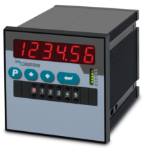
Features
- 2 pulse inputs with format A, B, 90° [HTL] or A, /A, B, /B [RS422]
- 4 control inputs for HTL / PNP / NPN / Namur signals [10 ... 30 VDC]
- Input frequency up to 300 kHz
- 4 fast transistor outputs, push-pull, short-circuit-proof [5 … 30 VDC]
- 1 scalable 14-bit analog output (±10 V or 0/4 … 20 mA)
- Loop time approx. 250 µs
- Defining incremental dimensions via keyboard or BCD decade switch on the front
- Power supply 24 VAC and 17 … 40 VDC
- Compact norm panel housing (according to EN 60715)
- Top hat rail mounting by using SM600 support brackets (option)
- Setup via keys or via PC by serial RS232 interface
- PROFIBUS connection via Motrona gateway PB251
- Dimension 96 x 96 x 140 mm (3,78 x 3,78 x 5,51")
-
Features
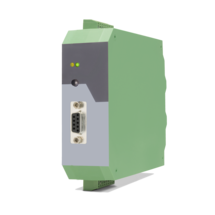
- Encoder input with format SIN+, SIN-, COS+, COS-, REF+, REF- [1 Vss]
- Control input „Error Release“ for PNP signals [10 ... 30 VDC]
- Input frequency up to 400 kHz
- Pulse output with format A, /A, B, /B, Z, /Z [RS422] or with format A, B, 90° [HTL]
- Output frequency up to 4 MHz [RS422]
- Control output „Error“ with push-pull characteristic, short-circuit-proof, [5 ... 30 VDC]
- Power supply 18 ... 30 VDC
- Snap-on housing for top-hat rail (according to EN 60715)
- Adjustable multiplier for interpolation rates from 1:5 to 1:50
- Adjustable divider 1:1 – 1:255 to reduce the output frequency
-
Features
- 1 encoder input with format SIN+, SIN-, COS+, COS-, REF+, REF- [1 Vss]
- Maximum sinus input frequency 500 kHz with max. 200 ns conversion time
- 2 signal outputs with format SIN+, SIN-, COS+, COS-, REF+, REF- [1 Vss]
- 2 pulse outputs with format A, /A, B, /B, Z, /Z [RS422, TTL, HTL]
- Power supply 17 ... 30 VDC
- Snap-on housing for top-hat rail (according to EN 60715)
-
Features
- 1 encoder input with format SIN+, SIN-, COS+, COS-, REF+, REF- [1 Vss]
- Maximum sinus input frequency 500 kHz with max. 200 ns conversion time
- 4 signal outputs with format SIN+, SIN-, COS+, COS-, REF+, REF- [1 Vss]
- Power supply 17 ... 30 VDC
- Snap-on housing for top-hat rail (according to EN 60715)
Page load link