Skip to content
Features
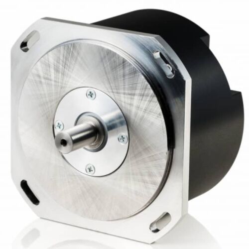
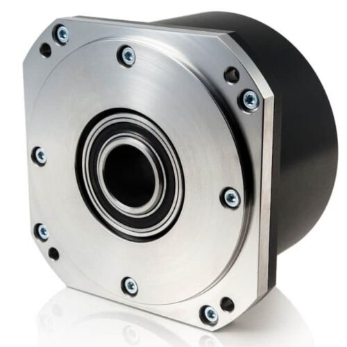
Number of output pulses per revolution 18000-1800000 ppr
Line number on disc (z) 18000
Reference signal - standard: 1 per shaft revolution
- distance coded: 36 per shaft revolution
Maximum shaft speed 5000 rpm
Maximum shaft load
- radial: 10 N
Accuracy ± 7.5 arc. sec; ± 5.0 arc. sec
Starting torque at 20°C ≤ 0.01 Nm
Rotor moment of inertia < 20x10-6 kgm2
Protection (IEC 529) IP64
Maximum weight without cable 0.7 kg
Operating temperature 0...+50°C
Storage temperature -30...+80°C
Maximum humidity (non-condensing) 98%
Permissible vibration (55 to 2000 Hz) ≤ 100 m/s²
Permissible shock (11 ms) ≤ 300m/s²
Features
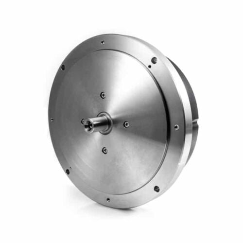
Number of output pulses per revolution 18000-1800000 ppr
Line number on disc (z) 18000; 36000
Reference signal
- standard: 1 per shaft revolution
- distance coded for z = 18000: 36 per shaft revolution
- distance coded for z = 36000: 72 per shaft revolution
Permissible mech. speed ≤ 1000 rpm
Max. operating speed 300 to 500 rpm
Accuracy ± 2.5 arc. sec
Permissible shaft load - axial: ≤ 30 N
- radial: ≤ 30 N
Starting torque at 20°C ≤ 0.012 Nm
Rotor moment of inertia < 3.7x10⁻⁴ kgm2
Protection (IEC 529) IP64
Maximum weight without cable 3.5 kg
Operating temperature 0...+70°C
Storage temperature -30...+85°C
Maximum humidity (non-condensing) 98%
Permissible vibration (55 to 2000 Hz) ≤ 100 m/s²
Permissible shock (11 ms) ≤ 300m/s²
Features
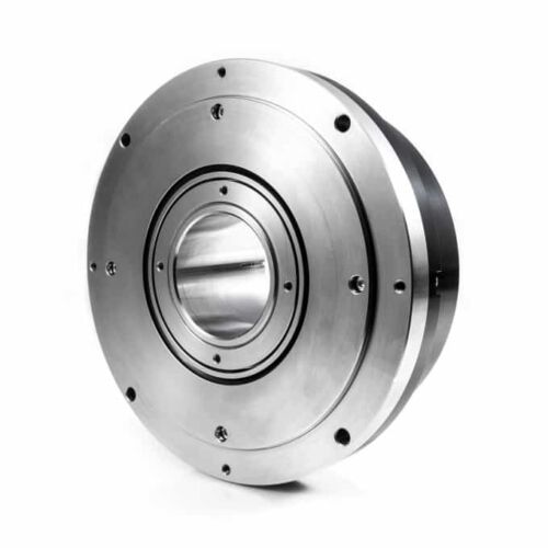
Number of output pulses per revolution 18000-1800000 ppr
Line number on disc (z) 18000; 36000
Reference signal
- standard: 1 per shaft revolution
- distance coded for z = 18000: 36 per shaft revolution
- distance coded for z = 36000: 72 per shaft revolution
Permissible mech. speed ≤ 1000 rpm
Max. operating speed 300 to 500 rpm
Accuracy ± 2.5 arc. sec
Permissible shaft load - axial: 0.02 mm
- radial: 0.02 mm
Starting torque at 20°C ≤ 0.012 Nm
Rotor moment of inertia < 3.7x10⁻⁴ kgm2
Protection (IEC 529) IP64
Maximum weight without cable 4.1 kg
Operating temperature 0...+70°C
Storage temperature -30...+85°C
Maximum humidity (non-condensing) 98%
Permissible vibration (55 to 2000 Hz) ≤ 100 m/s²
Permissible shock (11 ms) ≤ 300m/s²
Features
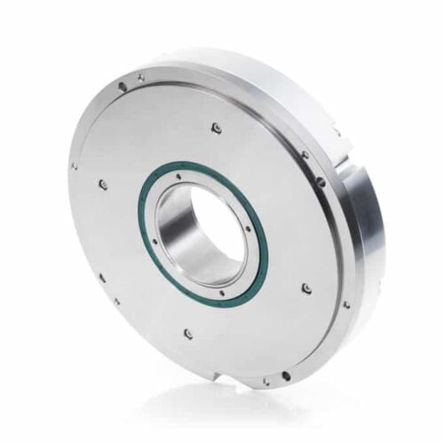
Number of output pulses per revolution 3.600.000
Line number on disc (z) 36000
Reference signal
- 1 per shaft revolution
- 36 per shaft revolution
- 72 per shaft revolution
Permissible mech. speed ≤ 1000 rpm
Max. operating speed 300 to 500 rpm
Accuracy ± 2.0 arc. sec
Permissible shaft load - axial: 0.02 mm
- radial: 0.02 mm
Starting torque at 20°C ≤ 0.5 Nm
Rotor moment of inertia < 0.9x10⁻³ kgm2
Protection (IEC 529) IP64
Maximum weight without cable 4.5 kg
Operating temperature 0...+70°C
Storage temperature -30...+85°C
Maximum humidity (non-condensing) 98%
Permissible vibration (55 to 2000 Hz) ≤ 100 m/s²
Permissible shock (11 ms) ≤ 300m/s²
Features
Number of output pulses per revolution 18000-1800000 ppr
Line number on disc (z) 18000
Reference signal - standard: 1 per shaft revolution
- distance coded: 36 per shaft revolution
Permissible mech. speed ≤ 3000 rpm
Max. operating speed 600 to 1000 rpm
Accuracy grades ± 5.0 arc. sec
Permissible shaft runout - axial: 0.02 mm
- radial: ± 0.02 mm
Starting torque at 20°C ≤ 0.08 Nm
Rotor moment of inertia < 0.6x10⁻⁴ kgm2
Protection (IEC 529) IP64
Maximum weight without cable 1.2 kg
Operating temperature 0...+70°C
Storage temperature -30...+85°C
Maximum humidity (non-condensing) 98%
Permissible vibration (55 to 2000 Hz) ≤ 100 m/s²
Features
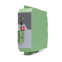
6-wire connection for one strain gauge full bridge sensor
4 control inputs [HTL/PNP]
1 analog output ±10 V, 0/4 ... 20 mA, 16 bit
4 control outputs for signalling different operation states
Power supply 18 ... 30 VDC
Functions for scaling and linking the sensor signals (e.g. A+B, A-B, ...)
Adjustable bridge voltage per sensor from 3 VDC ... 10 VDC
Sensitivity of the sensor inputs 1 ... 10 mV
Transmission of the sensor data via RS485
Programming via USB and the user interface OS (freeware)
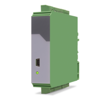
Protection class IP20
Compact housing for mounting on 35 mm top-hat rail (according to EN 60715)
Features
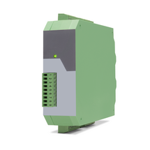
6-wire connection for two independent strain gauge full bridge sensors
4 control inputs [HTL/PNP]
2 independent analog outputs ±10 V, 0/4 ... 20 mA, 16 bit
4 control outputs for signalling different operation states
Power supply 18 ... 30 VDC
Functions for scaling and linking the sensor signals (e.g. A+B, A-B, ...)
Adjustable bridge voltage per sensor from 3 VDC ... 10 VDC
Sensitivity of the sensor inputs 1 ... 10 mV
Transmission of the sensor data via RS485
Programming via USB and the user interface OS (freeware)
Protection class IP20
Compact housing for mounting on 35 mm top-hat rail (according to EN 60715)
Features
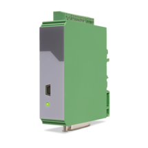
4 analog inputs for ±10 V or 0/4 ... 20 mA (2x current / 2x voltage)
optionally 3 control inputs for PNP signals [10 ... 30 VDC]
IO link interface
Power supply 12 ... 30 VDC
Compact housing for mounting on 35 mm DIN rail (according to EN 60715)
Features
1 Strain gauge input
3 VDC and 10 VDC bridge voltage per sensor connection
1 … 10 mV sensitivity
optionally 3 control inputs for PNP signals [10 ... 30 VDC]
IO link interface
Power supply 12 ... 30 VDC
Compact housing for mounting on 35 mm DIN rail (according to EN 60715)
Features
Start-stop interface for absolute transducers and magnetostrictive sensors
SSI input in the format DATA +, DATA-, CLOCK +, CLOCK- up to 32 bits
3 control inputs (hold) for PNP signals [10 ... 30 VDC]
Pulse inputs A, B [HTL], A, / A, B, / B [RS422, HTL]
Input frequency up to 1 MHz
25-bit parallel output push-pull in BCD, binary or Gray code format
Power supply 18 ... 30 VDC
Compact housing for mounting on 35 mm top-hat rail (according to EN 60715)
Features
2 pulse inputs with format A, B, 90° [HTL] or A, /A, B, /B [RS422]
4 control inputs for HTL / PNP / NPN / Namur signals [10 ... 30 VDC]
Input frequency up to 300 kHz
4 fast transistor outputs, push-pull, short-circuit-proof [5 … 30 VDC]
1 scalable 14-bit analog output (±10 V or 0/4 … 20 mA)
Loop time approx. 250 µs
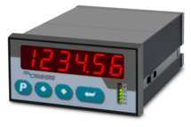
Defining incremental dimensions via keyboard
Power supply 24 VAC and 17 … 40 VDC
Compact norm panel housing (according to EN 60715)
Top hat rail mounting by using SM300 support brackets (option)
Setup via keys or via PC by serial RS232 interface
PROFIBUS connection via mMotrona gateway PB251
Features
2 pulse inputs with format A, B, 90° [HTL] or A, /A, B, /B [RS422]
4 control inputs for HTL / PNP / NPN / Namur signals [10 ... 30 VDC]
Input frequency up to 300 kHz
4 fast transistor outputs, push-pull, short-circuit-proof [5 … 30 VDC]
1 scalable 14-bit analog output (±10 V or 0/4 … 20 mA)
Loop time approx. 250 µs
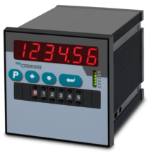
Defining incremental dimensions via keyboard or BCD decade switch on the front
Power supply 24 VAC and 17 … 40 VDC
Compact norm panel housing (according to EN 60715)
Top hat rail mounting by using SM600 support brackets (option)
Setup via keys or via PC by serial RS232 interface
PROFIBUS connection via Motrona gateway PB251
Dimension 96 x 96 x 140 mm (3,78 x 3,78 x 5,51")
Features
Start-stop interface for absolute transducers and magnetostrictive sensors
Adjustable frequency of the init pulses from 62.5 Hz to 5 kHz
Analog output ± 10 V, 0/4 ... 20 mA, 16 bit
Power supply 18 ... 30 VDC
Compact housing for mounting on a 35 mm top-hat rail (according to EN 60715)
Simple parameterization via the OS6.0 user interface
Serial RS232 / RS485 interface
Pulse inputs A, B [HTL], A, /A, B, /B [RS422, HTL]
SSI input DATA+, DATA-, CLOCK+, CLOCK- [RS422], 32 Bit
USB interface and RS232/RS485 interface for configuration and serial readout
Features
Scalable 14 bit analog input for ±10 V or 0/4 ... 20 mA
4 control inputs for PNP signals [10 ... 30 VDC]
Pulse output with format A, B, 90° [HTL] or A, /A, B, /B, Z, /Z [RS422]
SSI output with format DATA+, DATA-, CLOCK+, CLOCK- up to 25 bit
Power supply 12 ... 30 VDC
Snap-on housing for top-hat rail (according to EN 60715)
Various user modes: Programmable V / f characteristics, programmable curves with optionally repeating curve cycles, additional control functions similar to a “motorized potentiometer”
USB, RS232 and RS485 interface for programming and serial readout of the conversion result and other internal registers
Adjustable filter functions as well as operator programmable linearization curves
Printer mode for automatic data transfer of internal registers to a data logger or PC
Page load link