Skip to content
Features
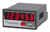
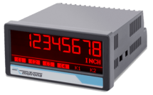
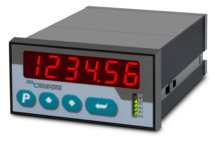
Scalable 14-bit analog input for 0 ... 10 V or 0/4 ... 20 mA
Power supply 24 VDC
Miniature norm panel housing
5 digits LED display with 8 mm height
Display range -19999 ... 99999, adjustable zero and full-scale value
Latch input to freeze the display, minimum/maximum record memory
Easy to set up with only two front keys and menu support
Delivery includes adapter frame for 50 x 25 mm cut out and label set with dimensions
Front dimension 48 x 24 x 59 mm (1.89 x 0.945 x 2.322")
Features
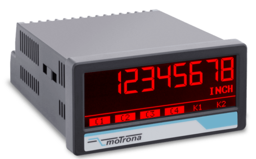
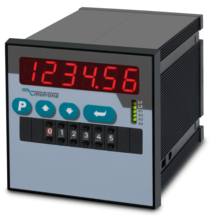
2 universal 16-bit analogue inputs for ±10 V or 0/4 … 20 mA
3 control inputs for HTL / PNP signals
Power supply 18 ... 30 VDC
24 V auxiliary output for encoder supply
High accuracy reference output 10 V for potentiometers > 1 kOhm
3.78 x 1.89-inch norm panel housing and IP65 protection
Bright and high-contrast display with event-dependent color variations
Emulation of a 7-segment display inclusively icons and units
Intuitive and easy parameterization by plain text and touchscreen
Operating modes for visualization of INPUT 1, INPUT 2 or combinations of IN1 + IN2, IN1 - IN2, IN1 x IN2, IN1: IN2
Numerous features, e. g. tara, filters, averaging
Linearization with 24 control points
Options
Option AC: Power supply 115 ... 230 VAC
Option AO: 16-bit analog output, 4 control outputs, serial RS232 interface
Option AR: 16-bit analog output, 4 control outputs, serial RS485 interface
Option CO: 4 control outputs, serial RS232 interface
Option CR: 4 control outputs, serial RS485 interface
Option RL: 2 relay outputs
Option IO: IO-Link Device V1.1
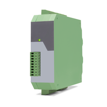
Features
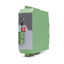
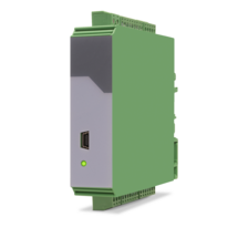
6-wire connection for one strain gauge full bridge sensor
4 control inputs [HTL/PNP]
1 analog output ±10 V, 0/4 ... 20 mA, 16 bit
4 control outputs for signalling different operation states
Power supply 18 ... 30 VDC
Functions for scaling and linking the sensor signals (e.g. A+B, A-B, ...)
Adjustable bridge voltage per sensor from 3 VDC ... 10 VDC
Sensitivity of the sensor inputs 1 ... 10 mV
Transmission of the sensor data via RS485
Programming via USB and the user interface OS (freeware)
Protection class IP20
Compact housing for mounting on 35 mm top-hat rail (according to EN 60715)
Features
6-wire connection for two independent strain gauge full bridge sensors
4 control inputs [HTL/PNP]
2 independent analog outputs ±10 V, 0/4 ... 20 mA, 16 bit
4 control outputs for signalling different operation states
Power supply 18 ... 30 VDC
Functions for scaling and linking the sensor signals (e.g. A+B, A-B, ...)
Adjustable bridge voltage per sensor from 3 VDC ... 10 VDC
Sensitivity of the sensor inputs 1 ... 10 mV
Transmission of the sensor data via RS485
Programming via USB and the user interface OS (freeware)
Protection class IP20
Compact housing for mounting on 35 mm top-hat rail (according to EN 60715)
Features
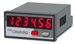
Single channel pulse input [HTL]
Input frequency up to 20 kHz
Programmable input filter for mechanical input contacts
Power supply 24 VDC
Miniature norm panel housing
6 digits LED display with 8 mm height
Display range -199999 ... 999999
Dimension B x H x T = 48 x 24 x 59 mm (1.89 x 0.94 x 2.32 ")
Features
Pulse input with format A, B, 90° [HTL], single channel as an option
HTL inputs for encoder and sensors with NPN / PNP or NAMUR switching characteristics
Input frequency up to 250 kHz
3 control inputs for HTL / PNP signals
Power supply 18 ... 30 VDC
24 V auxiliary output for encoder supply
3.78 x 1.89-inch norm panel housing and IP65 protection
Bright and high-contrast display with event-dependent color variations
Emulation of a 7-segment display inclusively icons and units
Intuitive and easy parameterization by plain text and touchscreen
Multi-functional device for speed, position, timer, counter or velocity application
Operating modes such as scaling, average filter, start-up suppression
Linearization with 24 control points
Options
Option AC: Power supply 115 ... 230 VAC
Option AO: 16-bit analog output, 4 control outputs, serial RS232 interface
Option AR: 16-bit analog output, 4 control outputs, serial RS485 interface
Option CO: 4 control outputs, serial RS232 interface
Option CR: 4 control outputs, serial RS485 interface
Option RL: 2 relay outputs
Options can be combined.
Features
2 Incremental inputs with format A, /A, B, /B
Differential, single-ended HTL / RS422
Input frequency up to 1 MHz
Power supply 18 ... 30 VDC
5 / 24 VDC auxiliary output for encoder supply
3.78 x 1.89-inch norm panel housing and IP65 protection
Bright and high-contrast display with event-dependent color variations
Emulation of a 7-segment display inclusively icons and units
Intuitive and easy parameterization by plain text and touchscreen
Multi-functional device for speed, process time, timer, counter or velocity application
Operating modes such as scaling, average filter, start-up suppression
Linearization with 24 control points
Options
Option AC: Power supply 115 ... 230 VAC
Option AO: 16-bit analog output, 4 control outputs, serial RS232 interface
Option AR: 16-bit analog output, 4 control outputs, serial RS485 interface
Option CO: 4 control outputs, serial RS232 interface
Option CR: 4 control outputs, serial RS485 interface
Option RL: 2 relay outputsOptions can be combined.
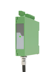
Features
4 analog inputs for ±10 V or 0/4 ... 20 mA (2x current / 2x voltage)
optionally 3 control inputs for PNP signals [10 ... 30 VDC]
IO link interface
Power supply 12 ... 30 VDC
Compact housing for mounting on 35 mm DIN rail (according to EN 60715)
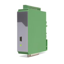
Features
1 Strain gauge input
3 VDC and 10 VDC bridge voltage per sensor connection
1 … 10 mV sensitivity
optionally 3 control inputs for PNP signals [10 ... 30 VDC]
IO link interface
Power supply 12 ... 30 VDC
Compact housing for mounting on 35 mm DIN rail (according to EN 60715)
Features
4 independent input channels with format A, B, C, D [HTL] or A, /A, B, /B, C, /C, D, /D [RS422], also possible for single-channel
4 output channels with format A, B, C, D [HTL] or A, /A, B, /B, C, /C, D, /D [RS422]
Maximum input frequency 1 MHz
Very short conversion time < 300 ns
Optical wavelength 1300 nm
Transmission distance up to 3000 meters
Power supply 5 VDC (for LW213)
Power supply 10 ... 30 VDC (for LW213-1, LW213-2, LW213-3)
Snap-on housing for top-hat rail (according to EN 60715)
Pre-configured optical fibres are available
Features
4 independent input channels with format A, B, C, D [HTL] or A, /A, B, /B, C, /C, D, /D [RS422], also possible for single channel
4 output channels with format A, B, C, D [HTL] or A, /A, B, /B, C, /C, D, /D [RS422]
Maximum input frequency 1 MHz
Very short conversion time < 300 ns
Optical wavelength 1300 nm
Transmission distances up to 3000 meters
Power supply 5 VDC (for LW214)
Power supply 10 ... 30 VDC (for LW214-1, LW214-2)
Snap-on housing for top-hat rail (according to EN 60715)
Pre-configured optical fibers are available
Features
4 independent input channels with format A, B, C, D [HTL] or A, /A, B, /B, C, /C, D, /D [RS422], also possible for single channel
4 output channels with format A, B, C, D [HTL] or A, /A, B, /B, C, /C, D, /D [RS422]
Maximum input frequency 1 MHz
Very short conversion time < 300 ns
Optical wavelength 850 nm
Transmission distance up to 2000 meters
Power supply 5 VDC (for LW215)
Power supply 10 ... 30 VDC (for LW215-1, LW215-2, LW216-3)
Snap-on housing for top-hat rail (according to EN 60715)
Pre-configured optical fibers are available
Features
4 independent input channels with format A, B, C, D [HTL] or A, /A, B, /B, C, /C, D, /D [RS422], also possible for single channel
4 output channels with format A, B, C, D [HTL] or A, /A, B, /B, C, /C, D, /D [RS422]
Maximum input frequency 1 MHz
Very short conversion time < 300 ns
Optical wavelength 850 nm
Transmission distance up to 2000 meters
Power supply 5 VDC (for LW216)
Power supply 10 ... 30 VDC (for LW216-1, LW216-2)
Snap-on housing for top-hat rail (according to EN 60715)
Pre-configured optical fibers are available
Features
1 SSI input / output channel [RS422] with format DATA+, DATA-, CLOCK+, CLOCK-
1 Error input (LW217) resp. 1 open-drain-output (LW218)
Maximum input frequency 1 MHz
Very short conversion time < 300 nsec.
Optical wavelength 850 nm
Transmission distance up to 2000 meters
Power supply 5 VDC (for LW217)
Power supply 10 ... 30 VDC (for LW217-1)
Free adjustable SSI resolution from 1 ... 99 bit
Snap-on housing for top-hat rail (according to EN 60715)
Pre-configured optical fibres are available
Features
1 SSI input / output channel [RS422] with format DATA+, DATA-, CLOCK+, CLOCK-
1 open-drain-output (LW218)
Maximum input frequency 1 MHz
Very short conversion time < 300 ns
Optical wavelength 1300 nm
Transmission distance up to 2000 meters
Power supply 5 VDC (for LW218)
Power supply 10 ... 30 VDC (for LW218-1)
Free adjustable SSI resolution from 1 ... 99 bit
Snap-on housing for top-hat rail (according to EN 60715)
Glass fibre cables are available ready-assembled
Features
Start-stop interface for absolute transducers and magnetostrictive sensors
SSI input in the format DATA +, DATA-, CLOCK +, CLOCK- up to 32 bits
3 control inputs (hold) for PNP signals [10 ... 30 VDC]
Pulse inputs A, B [HTL], A, / A, B, / B [RS422, HTL]
Input frequency up to 1 MHz
25-bit parallel output push-pull in BCD, binary or Gray code format
Power supply 18 ... 30 VDC
Compact housing for mounting on 35 mm top-hat rail (according to EN 60715)
Features
2 pulse inputs with format A, B, 90° [HTL] or A, /A, B, /B [RS422]
4 control inputs for HTL / PNP / NPN / Namur signals [10 ... 30 VDC]
Input frequency up to 300 kHz
4 fast transistor outputs, push-pull, short-circuit-proof [5 … 30 VDC]
1 scalable 14-bit analog output (±10 V or 0/4 … 20 mA)
Loop time approx. 250 µs
Defining incremental dimensions via keyboard
Power supply 24 VAC and 17 … 40 VDC
Compact norm panel housing (according to EN 60715)
Top hat rail mounting by using SM300 support brackets (option)
Setup via keys or via PC by serial RS232 interface
PROFIBUS connection via mMotrona gateway PB251
Features
2 pulse inputs with format A, B, 90° [HTL] or A, /A, B, /B [RS422]
4 control inputs for HTL / PNP / NPN / Namur signals [10 ... 30 VDC]
Input frequency up to 300 kHz
4 fast transistor outputs, push-pull, short-circuit-proof [5 … 30 VDC]
1 scalable 14-bit analog output (±10 V or 0/4 … 20 mA)
Loop time approx. 250 µs
Defining incremental dimensions via keyboard or BCD decade switch on the front
Power supply 24 VAC and 17 … 40 VDC
Compact norm panel housing (according to EN 60715)
Top hat rail mounting by using SM600 support brackets (option)
Setup via keys or via PC by serial RS232 interface
PROFIBUS connection via Motrona gateway PB251
Dimension 96 x 96 x 140 mm (3,78 x 3,78 x 5,51")
Features
Start-stop interface for absolute transducers and magnetostrictive sensors
Adjustable frequency of the init pulses from 62.5 Hz to 5 kHz
Analog output ± 10 V, 0/4 ... 20 mA, 16 bit
Power supply 18 ... 30 VDC
Compact housing for mounting on a 35 mm top-hat rail (according to EN 60715)
Simple parameterization via the OS6.0 user interface
Serial RS232 / RS485 interface
Pulse inputs A, B [HTL], A, /A, B, /B [RS422, HTL]
SSI input DATA+, DATA-, CLOCK+, CLOCK- [RS422], 32 Bit
USB interface and RS232/RS485 interface for configuration and serial readout
Features
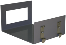
Support brackets with a snap mechanism for easy installation of panel housings onto a 35 mm DIN rail (according to EN 60715)
Suitable for display units with front dimensions of 96 x 48 mm
Features
Support brackets with a snap mechanism for easy installation of panel housings onto a 35 mm DIN rail (according to EN 60715)
Suitable for display units with front dimensions of 96 x 96 mm
Features
Scalable 14 bit analog input for ±10 V or 0/4 ... 20 mA
4 control inputs for PNP signals [10 ... 30 VDC]
Pulse output with format A, B, 90° [HTL] or A, /A, B, /B, Z, /Z [RS422]
SSI output with format DATA+, DATA-, CLOCK+, CLOCK- up to 25 bit
Power supply 12 ... 30 VDC
Snap-on housing for top-hat rail (according to EN 60715)
Various user modes: Programmable V / f characteristics, programmable curves with optionally repeating curve cycles, additional control functions similar to a “motorized potentiometer”
USB, RS232 and RS485 interface for programming and serial readout of the conversion result and other internal registers
Adjustable filter functions as well as operator programmable linearization curves
Printer mode for automatic data transfer of internal registers to a data logger or PC
Page load link