Skip to content
Features
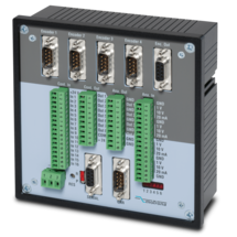
MC700 is a universal motion controller for 1 to 4 axes, which can be assigned any motion control functions by loading firmware. Together with the firmware BY701 (see firmware), this controller offers excellent synchronous functions for 1 - 4 axes.The firmware offers all conceivable possibilities for the synchronization of drives, including the influence of phase position and the relative position between the drives and numerous index and print mark functions.
Optionally, a "physical master" or the built-in "virtual master axis" with programmable speeds and ramps can be used as the master drive.
The number of successive axes can be extended arbitrarily via a cascading output.
MC700 controllers can be operated via an external control terminal, serial interface or optional via CANBUS (MC700/CI). PC operator software is included.
PROFIBUS connection possible via gateway PB251 (see accessories)
Features
Strain gauge input, 6-wire connection
Input pt100 and thermocouples (J and K)
3 control inputs for HTL / PNP signals
Power supply 18 ... 30 VDC
Adjustable bridge voltage 3 VDC to 10 VDC
1 … 10 mV sensitivity
Standard installation housing with 96 x 48 mm and protection class IP65
Bright and high-contrast graphic display with event-dependent color variants
Emulation of a 7-segment display with symbols and units
Intuitive and simple parameterization through plain text and touchscreen
Numerous functions such as tare, filter, averaging
Linearization with 24 support points
Options
Option AC: Power supply 115 ... 230 VAC
Option AO: 16-bit analog output, 4 control outputs, serial RS232 interface
Option AR: 16-bit analog output, 4 control outputs, serial RS485 interface
Option CO: 4 control outputs, serial RS232 interface
Option CR: 4 control outputs, serial RS485 interface
Option RL: 2 relay outputs
Option IO: IO-Link Device V1.1
Options can be combined.
Features
Control input with format [HTL]
2 SSI inputs with format [RS422]
Cutt-off frequency 100 kHz ... 1 MHz
2 encoder inputs, short-circuit-proof
1 SSI output with format [RS422]
Power supply 12 ... 30 V DC
Current consumption (unloaded) 50 mA
Encoder supply 2 x 125mA (Vin – 2 V) short-circuit-proof
Delay / Output / Input100 ns
Operation temperature : 0 ... 45 °C (32 ... 113 °F)
SSI pause time min. 25 ns
Switching time is synchronized automatically with the next SSI break
Cascadable for more SSI encoders
All connections via pluggable screw terminal block
Snap-on housing for top-hat rail (according to EN 60715)
LEDs for indication of the input pulses
Dimension W x H x D = 22,5 x 121 x 112 mm (8.86 x 47.64 x 44.09'')
Plastic housing incl. plug
Features
2 pulse inputs with format A, B, Z [HTL] or A, /A, B, /B, Z, /Z [RS422]
Input frequency up to 250 kHz for asymmetrical and up to 1 MHz for symmetric signals
2 control inputs for HTL / PNP signals [10 ... 30 VDC]
2 output channels with format A, B, Z [HTL] or A, /A, B, /B, Z, /Z [RS422], each output adjustable separately
Power supply 12 ... 30 VDC
Snap-on housing for top-hat rail (according to EN 60715)
Features
4 analog inputs for ±10 V or 0/4 ... 20 mA (2x current / 2x voltage)
optionally 3 control inputs for PNP signals [10 ... 30 VDC]
IO link interface
Power supply 12 ... 30 VDC
Compact housing for mounting on 35 mm DIN rail (according to EN 60715)
Features
1 SSI input (10 … 32 bit)
for single-turn and multiturn encoders
optionally 3 control inputs for PNP signals [10 ... 30 VDC]
IO link interface
Power supply 12 ... 30 VDC
Compact housing for mounting on 35 mm DIN rail (according to EN 60715)
Features
SSI input with format DATA+, DATA-, CLOCK+, CLOCK- up to 32 Bit
Impulse inputs A, B [HTL], A, /A, B, /B [RS422, HTL]
3 control inputs (Hold) for PNP signals [10 ... 30 VDC]
Start-stop interface for absolute transducers and magnetostrictive sensors
Input frequency up to 1 MHz
25-bit parallel output push-pull in BCD, binary or Gray code format
Power supply 18 ... 30 VDC
Compact housing for mounting on 35 mm top-hat rail (according to EN 60715)
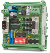
Features
Pulse input in format A, /A, B, /B, Z, /Z [RS422, HTL]
Pulse input in format A, B, Z [HTL]
Input frequency up to 1 MHz
Pulse output in format A, /A, B, /B, Z, /Z [RS422, HTL]
Pulse output in format A, B, Z [HTL]
Power supply 9 ... 30 VDC
Settings via DIL switches
Level conversion (RS422, HTL single-ended, HTL differential, TTL and vice versa)
Division of two-track A / B pulses with adjustable ratio 1: 1 to 1: 4096
Division of the Z pulse with adjustable ratio 1: 1 to 1: 256
External HTL signals for various functions
Implementation between the two types of representations for the direction of rotation (A / B 90 °, A/B Dir and vice versa, Division possible)
Snap-on housing for top-hat rail (acc. EN 60715)
Dimension (B x H X T) 22,5 x 102 x 102 mm
Features
SSI input DATA+, DATA-, CLOCK+, CLOCK- [RS422], 32 Bit
SSI clock frequency up to 1 MHz
Analog output ±10 V or 0/4 ... 20 mA, 16 Bit
Power supply 18 ... 30 VDC
Snap-on housing for top-hat rail (according to EN 60715)
Setup via operator software OS6.0
Serial RS232- / RS485 interface
Pulse inputs A, B [HTL], A, /A, B, /B [RS422, HTL]
Start-stop interface for absolute transducers and magnetostrictive sensors
USB interface and RS232/RS485 interface for configuration and serial readout
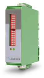
Features
20-bit parallel input with format BCD, binary or Gray-Code
Input frequency: fast encoder 5 kHz, auto-transmit / data logging 0.5 kHz
4 status outputs, with push-pull characteristics, short-circuit-proof [5 ... 30 VDC]
Power supply 10 ... 30 VDC
Snap-on housing for top-hat rail (according to EN 60715)
Serial RS232 / RS485 interface
Features
Pulse input with format A, B, Z [HTL] (10 ... 30 V)
Input frequency max. 200 kHz
Pulse output with format A, /A, B, /B, Z, /Z [RS422 / TTL]
Power supply 5 VDC
Converts HTL levels (A / B / Z) in TTL / RS422, incl. the inverted signals
Converts also static/separate directional information into a dual channel A / B signal with a 90° phase shift
Open print version with plastic snap-on housing for top-hat rail (according to EN 60715)
Features
Pulse input with format A, /A, B, /B, Z, /Z [TTL / RS422]
Input frequency max. 200 kHz
Pulse output with format A, B, Z [HTL]
Power supply 10 ... 30 VDC
Converts TTL / RS422 signals (A, /A, B, /B, Z, /Z) in HTL format with an output level of 10 ... 30 VDC
Generates additionally an A / B directional information with 90° phase shift‚ a static HIGH / LOW directional signal or separate directional pulses
Open print version with plastic snap-on housing for top-hat rail (according to EN 60715)
Features
1 pulse input with format A, B, Z [HTL] or A, /A, B, /B, Z, /Z [RS422]
Input frequency up to 500 kHz
1 pulse output with format A, /A, B, /B, Z, /Z [RS422, HTL]
Power supply 5 ... 30 VDC
Potential separation between input and output
Possibility to convert A, B / 90 ° directional information into static directional signal and vice versa
Connections on the input as well as on the output either via sub-D plugs or plug-in screw terminals (parallel connections)
Snap-on housing for top-hat rail (according to EN 60715)
Features
Encoder input with format SIN+, SIN-, COS+, COS-, REF+, REF- [1 Vss]
Control input „Error Release“ for PNP signals [10 ... 30 VDC]
Input frequency up to 400 kHz
Pulse output with format A, /A, B, /B, Z, /Z [RS422] or with format A, B, 90° [HTL]
Output frequency up to 4 MHz [RS422]
Control output „Error“ with push-pull characteristic, short-circuit-proof, [5 ... 30 VDC]
Power supply 18 ... 30 VDC
Snap-on housing for top-hat rail (according to EN 60715)
Adjustable multiplier for interpolation rates from 1:5 to 1:50
Adjustable divider 1:1 – 1:255 to reduce the output frequency
Features
1 encoder input with format SIN+, SIN-, COS+, COS-, REF+, REF- [1 Vss]
Maximum sinus input frequency 500 kHz with max. 200 ns conversion time
2 signal outputs with format SIN+, SIN-, COS+, COS-, REF+, REF- [1 Vss]
2 pulse outputs with format A, /A, B, /B, Z, /Z [RS422, TTL, HTL]
Power supply 17 ... 30 VDC
Snap-on housing for top-hat rail (according to EN 60715)
Features
1 encoder input with format SIN+, SIN-, COS+, COS-, REF+, REF- [1 Vss]
Maximum sinus input frequency 500 kHz with max. 200 ns conversion time
4 signal outputs with format SIN+, SIN-, COS+, COS-, REF+, REF- [1 Vss]
Power supply 17 ... 30 VDC
Snap-on housing for top-hat rail (according to EN 60715)
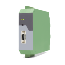
Features
Suitable for display units with front dimensions 96 x 48 mm
(fits not to Profibus indicator PB340)
Protection class IP65
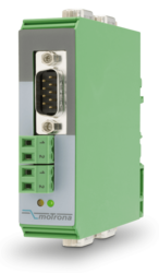
Features
Scalable 14 bit analog input for ±10 V or 0/4 ... 20 mA
4 control inputs for PNP signals [10 ... 30 VDC]
Pulse output with format A, B, 90° [HTL] or A, /A, B, /B, Z, /Z [RS422]
SSI output with format DATA+, DATA-, CLOCK+, CLOCK- up to 25 bit
Power supply 12 ... 30 VDC
Snap-on housing for top-hat rail (according to EN 60715)
Various user modes: Programmable V / f characteristics, programmable curves with optionally repeating curve cycles, additional control functions similar to a “motorized potentiometer”
USB, RS232 and RS485 interface for programming and serial readout of the conversion result and other internal registers
Adjustable filter functions as well as operator programmable linearization curves
Printer mode for automatic data transfer of internal registers to a data logger or PC
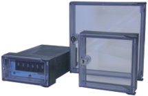
Features
To increase the protection class in dusty or wet environments, several types of protection caps are available for motrona units.
Some of the elastic and transparent plastic caps allow you to operate the keypad or to set the thumbwheel switches behind the cap, without removing it.
Page load link